
Remote Blower Install
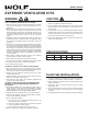


MODEL 801640
Page 2
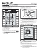
20½"
11"
dia.
hole
20½"
10
3
/
8"
1¼"
dia. hole
10
3
/
8"
8½"
8½"
20¾"
20¾"
7¼"
7¼"
1¼"
dia. hole
9
1
/
8"
9
1
/
8"
REMOVE
SHINGLES
Roof Rafter
REMOVE
SHINGLES
11"
dia.
hole
Roof Rafter
Pilot
Pilot
Hole
Hole
Pilot
Hole
OUTSIDE - ROOF VIEW
OUTSIDE - ROOF VIEW
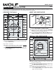
7"
2"
29½"
25"
2"
For flat roof installations:
q 4
Build a curb that will mount the blower at a minimum pitch
of 2/12. Discharge end of the blower should be pointed
away from prevailing winds.
ROOF MOUNT
INSTALLATION
For use with Wolf CTWH30/CTWH36 wall mount, IH4227 island chimney hoods, 10” tall & 30” wide x 18” tall wall hoods.
PREPARE THE ROOF
INSTALL THE VENTILATOR
OUTSIDE - ROOF VIEW
OUTSIDE - ROOF VIEW
OUTSIDE - ROOF VIEW
OUTSIDE - ROOF VIEW
7 Cover
7 Cover
Screws
Screws
7 Cover
Screws
6
Mounting
Holes
6
Mounting
Holes
Shipping
Cardboard
Shipping
Cardboard
Remove
roofing
nails from
top 2/3 of
shingles.
Remove
roofing
nails from
top 2/3 of
shingles.
Flashing Sheet
Bird Screen
Bird Screen
Wiring
Cover
WIRE THE VENTILATOR
From inside the attic space:
q 1
Drill a PILOT HOLE up through the roof, 8½" from the
inside edge of a ROOF RAFTER.
From outside - on the roof:
q 2
Measure and mark the 20¾" x 20½" rectangle. Cut and
remove only the shingles inside this rectangle.
q 3
Measure and mark the 11" DIAMETER HOLE and the
1¼" DIAMETER HOLE. Cut these holes all the way through
the roof.
q 8
Remove SHIPPING CARDBOARD from blower wheel.
q 9
Remove roofing nails from top 2/3 of shingles around cut-
out area.
q 10
Slide the ventilator's FLASHING SHEET up and under
the loosened shingles until ventilator's discharge collar
fits into 11" diameter hole.
q 11
Use the 6 screws (provided) to attach the ventilator to the
roof. 6 MOUNTING HOLES are provided.
q 12
Seal the screw heads, loosened shingles, and edges of
the flashing sheet, with a good grade of roofing cement.
q 13
Check for free movement of the spring-loaded damper,
re-install BIRD SCREEN and ventilator cover. Turn on
power and check operation.
120 VAC
LINE IN
BLACK
TO
BLACK
WHITE
TO
WHITE
GREEN
TO
GREEN
q 5
Remove 7 COVER SCREWS and lift off ventilator cover.
Remove BIRD SCREEN and WIRING COVER.
q 6
Feed the electric power cable through the 1¼" DIAMETER
HOLE and connect cable to ventilator with a proper
connector for the type of cable being used.
q 7
Connect BLACK TO BLACK, WHITE TO WHITE, and the
GREEN TO GREEN or bare wire. Replace wiring cover.