Downdraft Ventilation Installation Guide
DOWNDRAFT VENTILATION Contents 3 Downdraft Important Note Ventilation 4 Specifications 7 Installation Troubleshooting 11 Features and specifications are subject to change at any time without notice. Visit wolfappliance.com/specs for the most up-to-date information.
DOWNDRAFT VENTILATION Product Information Important product information including the model and serial number are listed on the product rating plate. The rating plate is located next to the blower housing on the front side of the downdraft, below the countertop. Refer to the illustration below. If service is necessary, contact Wolf factory certified service with the model and serial number.
SPECIFICATIONS Installation Requirements Electrical For installation with a Wolf cooktop, a minimum 25 1/8" (638) deep flat countertop is required. Installation must be electrically grounded in accordance with local codes or, in the absence of local codes, with the National Electrical Code, ANSI/NFPA 70. For installation with a sealed burner rangetop, an accessory trim kit is required. Contact your authorized Wolf dealer for details.
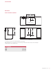
SPECIFICATIONS Downdraft INSTALLATION WITH COOKTOP W DOWNDRAFT CUT-OUT WIDTH 2 11/16" (68) E 8 1/4" (210)* COOKTOP CUT-OUT TOP VIEW 8 1/4" (210)* 211/4" 211/4" 23 3/8" (540) (540) (594) E SIDE VIEW FRONT VIEW *6" (152) back from countertop cut-out when internal blower is rear mounted. NOTE: Internal blower 6" (152) round, side, rear or bottom discharge. In-line and remote blower 10" (254) round, rear discharge. Centerline indicates center of downdraft cut-out.
SPECIFICATIONS Downdraft INSTALLATION WITH SEALED BURNER RANGETOP W DOWNDRAFT CUT-OUT WIDTH 2 11/16" (68) E 8 1/4" (210)* RANGETOP OPENING TOP VIEW 19" (483) PLATFORM DEPTH 211/4" 211/4" 23 3/8" (540) (540) (594) 8 1/4" (210)* E SIDE VIEW FRONT VIEW *6" (152) back from countertop cut-out when internal blower is rear mounted. NOTE: Internal blower 6" (152) round, side, rear or bottom discharge. In-line and remote blower 10" (254) round, rear discharge.
INSTALLATION Installation DOWNDRAFT TRANSITION 1 Install For internal blowers, remove the existing 10" (254) round transition. Refer to the illustration below. 2 Install For in-line and remote blowers being discharged from the front, leave the 10" (254) round transition in place. the top mounting brackets using the #4 sheet metal screws provided. Refer to the illustration below. the lower mounting brackets using the #8 x 32 sheet metal screws provided, but do not tighten.
INSTALLATION Installation INTERNAL BLOWER o mount the internal blower on the front or rear of the T downdraft: 1 Rotate the blower box so the 6" (152) round discharge is properly located, then disconnect the cable from the downdraft receptacle and connect it to the blower receptacle. Refer to the illustrations below. 2 Once the blower connection is made and the discharge properly located, secure the blower to the downdraft using the four screws provided.
INSTALLATION Installation IN-LINE / REMOTE BLOWER COUNTERTOP MOUNTING 1 Insert Place the downdraft in the opening, then secure the bottom brackets to the cabinet base using the wood screws provided. Once the brackets are secure, tighten the existing lower bracket screws. Refer to the illustration below. the electrical supply (Romex) from the in-line or remote blower through the opening on the downdraft and secure using an approved cord strain relief.
INSTALLATION Installation CONTROL MODULE TOP COVER 1 Use Plug the downdraft power cord into a grounded 3-prong receptacle, then route beneath the appliance and away from heat generated by the cooktop. Check downdraft operation. the template provided on page 11 to mark holes for mounting screws. Drill one 1 9/16" (40) in the center and two 3/8" (10) holes for the mounting screws. CAUTION Verify the scale of the template if not using the installation guide shipped with the downdraft.
INSTALLATION Troubleshooting Control Module Template IMPORTANT NOTE: If the downdraft ventilation system does not operate properly, follow these troubleshooting steps: • Verify electrical power is supplied to the downdraft. • Verify proper electrical connections. 13/16" (21) • If the downdraft does not operate properly, contact Wolf factory certified service. Do not attempt to repair the downdraft. Wolf is not responsible for service required to correct a faulty installation.
VENTILACIÓN DE TIRO DESCENDENTE Contenido 3 Ventilación Aviso importante de tiro descendente 4 Especificaciones 7 Instalación Resolución de problemas 11 Las características y especificaciones están sujetas a cambios sin previo aviso. Visite wolfappliance.com/specs para obtener la información más actualizada.
VENTILACIÓN DE TIRO DESCENDENTE Información del producto La información importante del producto, incluido el modelo y número de serie de la unidad, se encuentra en la placa de datos del producto. La placa de datos se encuentra al lado de la cubierta del extractor en la parte frontal del tiro descendente, debajo del mostrador. Consulte la siguiente ilustración. Si necesita servicio, póngase en contacto con el centro de servicio autorizado de Wolf y tenga a la mano el modelo y número de serie de la unidad.
ESPECIFICACIONES Requisitos de instalación Instalación eléctrica Para instalarlo con una estufa Wolf, se necesita un mostrador plano de 251/8" (638) de profundidad. La instalación debe tener una conexión a tierra de conformidad con los códigos locales o, en ausencia de códigos locales, con el Código Nacional de Electricidad, ANSI/NFPA 70. Para instalarlo con una estufa con quemadores sellados, se necesita un kit de accesorios de ribetes.
ESPECIFICACIONES Ventilador de tiro descendente INSTALACIÓN CON ESTUFA W ANCHURA DEL RECORTE PARA EL VENTILADOR DE TIRO DESCENDENTE 2 11/16" (68) E 8 1/4" (210)* RECORTE PARA ESTUFA VISTA SUPERIOR 8 1/4" (210)* 211/4" 211/4" 23 3/8" (540) (540) (594) E VISTA LATERAL VISTA FRONTAL *6" (152) detrás del recorte del mostrador cuando el extractor interno está montado en la parte posterior.
ESPECIFICACIONES Ventilador de tiro descendente INSTALACIÓN CON ESTUFA CON QUEMADORES SELLADOS W ANCHURA DEL RECORTE PARA EL VENTILADOR DE TIRO DESCENDENTE 2 11/16" (68) E 8 1/4" (210)* ABERTURA PARA ESTUFA VISTA SUPERIOR 19" (483) PROFUNDIDAD DE LA PLATAFORMA 211/4" 211/4" 23 3/8" (540) (540) (594) 8 1/4" (210)* E VISTA LATERAL VISTA FRONTAL *6" (152) detrás del recorte del mostrador cuando el extractor interno está montado en la parte posterior.
INSTALACIÓN Instalación VENTILADOR DE TIRO DESCENDENTE TRANSICIÓN 1 Instale ara los extractores internos, retire la transición circular de P 10" (254) existente. Consulte la siguiente ilustración. los soportes de montaje superior con los tornillos de metal #4 proporcionados. Consulte la siguiente ilustración. 2 Instale los soportes de montaje inferior con los tornillos de metal #8 x 32 proporcionados, pero no los apriete.
INSTALACIÓN Instalación EXTRACTOR INTERNO ara montar el extractor interno al frente o en la parte de P atrás del tiro descendente: 1 Gire la caja del extractor de tal manera que el escape circular de 6" (152) se encuentre en el lugar apropiado, a continuación desconecte el cable del receptáculo del tiro descendente y conéctelo al receptáculo del extractor. Consulte las siguientes ilustraciones.
INSTALACIÓN Instalación EXTRACTOR EN LÍNEA/REMOTO MONTAJE DEL MOSTRADOR 1 Inserte Coloque el tiro descendente en la abertura, a continuación asegure los soportes inferiores al gabinete con los tornillos para madera proporcionados. Una vez que los soportes estén asegurados, apriete los tornillos existentes del soporte inferior. Consulte la siguiente ilustración.
INSTALACIÓN Instalación MÓDULO DE CONTROL CUBIERTA SUPERIOR tilice la plantilla proporcionada en la página 11 para U marcar los orificios para los tornillos de montaje. Taladre un orificio de 19/16" (40) en el centro y dos de 3/8" (10) para los tornillos de montaje. 1 PRECAUCIÓN Verifique la escala de la plantilla si no va utilizar la guía de instalación enviada con el tiro descendente.
INSTALACIÓN Resolución de problemas Plantilla del módulo de control AVISO IMPORTANTE: si el sistema de ventilación de tiro descendente no tiene un funcionamiento apropiado, siga estos pasos para resolver los problemas: 13/16" • Compruebe que el tiro descendente tenga corriente eléctrica. (21) • Compruebe que las conexiones eléctricas son las adecuadas. • Si el tiro descendente no funciona correctamente, póngase en contacto con el centro de servicio autorizado de Wolf.
VENTILATION À ASPIRATION DESCENDANTE Table des matières Remarque importante 3 Ventilation Pour s´assurer que ce produit est installé et utilisé en toute sécurité et aussi efficacement que possible, prenez note des types de renseignement mis en évidence tout au long de ce guide : à aspiration descendante 4 Spécifications 7 Installation Dépannage 11 REMARQUE IMPORTANTE met en évidence des renseigne- ments qui sont particulièrement importants.
VENTILATION À ASPIRATION DESCENDANTE Renseignements sur le produit Des renseignements importants sur le produit, y compris les numéros de modèle et de série, se trouvent sur la plaque signalétique du produit. La plaque signalétique est située à côté du boîtier de la soufflerie sur le devant de l´aspiration descendante, sous le comptoir. Reportez-vous à l´illustration ci-dessous. Si vous avez besoin de service, communiquez avec le service Wolf certifié par l´usine avec les numéros de modèle et de série.
SPÉCIFICATIONS Exigences d´installation Électricité Pour l´installation avec une surface de cuisson Wolf, un comptoir plat d´au moins 251/8 po (638) de profondeur est requis. L´installation doit être mise à la terre électriquement conformément aux codes locaux ou, en l´absence de codes locaux, conformément au code national de l´électricité, ANSI/NFPA 70. Pour l´installation avec un dessus de cuisinière à brûleur scellé, une trousse de garniture accessoire est requise.
SPÉCIFICATIONS Aspiration descendante INSTALLATION AVEC SURFACE DE CUISSON L LARGEUR DE LA DÉCOUPE DE L’ASPIRATION DESCENDANTE 2 11/16 po (68) E 8 1/4 po (210)* DÉCOUPE DE LA SURFACE DE CUISSON VUE DE DESSUS 8 1/4 po 211/4 po 211/4 po 23 3/8 po (210)* (540) (540) (594) E VUE DE PROFIL VUE DE FACE *6 po (152) de l’arrière de la découpe du comptoir lorsque la soufflerie interne est installée à l’arrière.
SPÉCIFICATIONS Aspiration descendante INSTALLATION AVEC DESSUS DE CUISINIÈRE À BRÛLEUR SCELLÉ L LARGEUR DE LA DÉCOUPE DE L’ASPIRATION DESCENDANTE 2 11/16 po (68) E 8 1/4 po (210)* OUVERTURE DU DESSUS DE CUISINIÈRE VUE DE DESSUS 19 po (483) PROFONDEUR DE LA PLATE-FORME 211/4 po 211/4 po 23 3/8 po (540) (540) (594) 8 1/4 po (210)* E VUE DE PROFIL VUE DE FACE *6 po (152) de l’arrière de la découpe du comptoir lorsque la soufflerie interne est installée à l’arrière.
INSTALLATION Installation ASPIRATION DESCENDANTE TRANSITION 1 Installez our les souffleries internes, retirez la transition ronde P existante de 10 po (254). Reportez-vous à l´illustration ci-dessous. 2 Installez Pour les souffleries en ligne et à distance évacuées vers l´avant, laissez la transition ronde de 10 po (254) en place. les supports de montage supérieurs au moyen des vis autotaraudeuses n° 4 fournies. Reportez-vous à l´illustration ci-dessous.
INSTALLATION Installation SOUFFLERIE INTERNE our installer la soufflerie interne sur l´avant ou l´arrière de P l´aspiration descendante : 1 Pivotez la boîte de la soufflerie afin que l´évacuation ronde de 6 po (152) soit correctement placée, puis débranchez le câble de la prise de l´aspiration descendante et branchez-le sur la prise de la soufflerie. Reportez-vous aux illustrations ci-dessous.
INSTALLATION Installation SOUFFLERIE EN LIGNE/À DISTANCE MONTAGE SUR UN COMPTOIR 1 Insérez Placez l´aspiration descendante dans l´ouverture, puis fixez les supports inférieurs à la base de l´armoire au moyen des vis à bois fournies. Une fois les supports fixés, serrez les vis du support inférieur existant. Reportez-vous à l´illustration ci-dessous.
INSTALLATION Installation MODULE DE COMMANDE COUVERCLE SUPÉRIEUR tilisez le gabarit fourni à la page 11 pour marquer les U trous pour les vis de montage. Percez un trou de 19/16 po (40) au centre et deux trous de 3/8 po (10) pour les vis de montage. 1 MISE EN GARDE Vérifiez l´échelle sur le gabarit si vous n´utilisez pas le guide d´installation expédié avec l´aspiration descendante.
INSTALLATION Dépannage Gabarit du module de commande REMARQUE IMPORTANTE : si le système de ventilation à aspiration descendante ne fonctionne pas correctement, suivez ces étapes de dépannage : • Assurez-vous que l´aspiration descendante est alimentée. 13/16 po (21) • Vérifiez les connexions électriques. • Si l´aspiration descendante ne fonctionne pas correctement, communiquez avec le service Wolf certifié par l´usine. Ne tentez pas de réparer l´aspiration descendante.
WOLF APPLIANCE, INC. P.O. BOX 44848 MADISON, WI 53744 808256 REV-E WOLFAPPLIANCE.COM 2 / 2014 800.222.