
Installation guide


10
|
Wolf Customer Care 800.222.7820
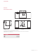
TOP COVER
Plug the downdraft power cord into a grounded 3-prong
receptacle, then route beneath the appliance and away from
heat generated by the cooktop. Check downdraft operation.
Once operation is veried, raise the chimney and install the
top trim using the three nuts provided. Verify the top trim is
properly aligned with the side covers. Refer to the illustra-
tion below.
FILTERS
Remove stickers and shipping brackets and install lters.
Refer to the illustration below.
TOP COVER
MELT
HIGH
OFF ON
OFF ON
SIM
HIGH
OFF ON
SIM
HIGH
BRIDGE
OFF ON
SIM
HIGH
ZONE 2
CLEAR
OFF
O
ZONE 2
ZONE 3
HIGH
SIM
OFF ON
Top cover installation.
Filter installation.
Installation
CONTROL MODULE
1 Use the template provided on page 11 to mark holes for
mounting screws. Drill one 1
9
/16" (40) in the center and
two
3
/8" (10) holes for the mounting screws.
CAUTION
Verify the scale of the template if not using the installa-
tion guide shipped with the downdraft.
2 Check countertop thickness to make sure threaded
studs are long enough to allow thumbnuts to fully
engage. Thicker countertops may require the countertop
be countersunk from below.
3 Place the control module on the countertop then secure
using the two nuts provided. Once secure, install the
ground wire and nut.
4 Use provided cable or cable designated by the National
Electric Code, NFPA/ANSI 70 or local codes. Connect
one end of the control cable to back side of control
module and other to electrical connection on front of
downdraft assembly. Ensure all connections are tight.
WARNING
Do not connect to telecommunication network.
RJ45
CONNECTOR
GROUND
RJ45
CONNECTOR
GROUND
NUT
CONTROL MODULE
COUNTERTOP
Downdraft connection.
Control module connection.
INSTALLATION