Dual Fuel Ranges Installation Guide
DUAL FUEL RANGES Contents Important Note 3 Safety To ensure this product is installed and operated as safely and efficiently as possible, take note of the following types of highlighted information throughout this guide: Precautions 4 Specifications 7 Installation Troubleshooting 11 Features and specifications are subject to change at any time without notice. Visit wolfappliance.com/specs for the most up-to-date information. IMPORTANT NOTE highlights information that is especially important.
SAFETY PRECAUTIONS Product Information Important product information including the model and serial number are listed on the product rating plate. The rating plate is located on the bottom of the control panel assembly, at the far right, just above the oven door. Refer to the illustration below. If service is necessary, contact Wolf factory certified service with the model and serial number.
SPECIFICATIONS Installation Requirements Electrical IMPORTANT NOTE: When installing against a combustible surface, a minimum 10" (254) riser is required for a 36" dual fuel range with charbroiler or griddle and all 48" and 60" models. Follow all minimum clearances to combustible surfaces shown in the illustration on the following pages. Installation must comply with all applicable electrical codes.
SPECIFICATIONS Gas Supply Installation must conform with local codes or, in the absence of local codes, with the National Fuel Gas Code. Locate the gas supply within the shaded area shown in the illustration on the following page. The range is equipped for use with natural or liquid propane (LP) gas. It is design certified by the Canadian Standards Association (CSA) for natural or LP gases. The product rating plate has information on the type of gas that should be used.
SPECIFICATIONS Dual Fuel Range INSTALLATION 13" 18" 30" (762) TO 36" (914) (330) (457) TO BOTTOM OF VENTILATION HOOD* 6" (152) W OPENING WIDTH 36 7/8" (937) TO COOKING SURFACE LOCATION OF GAS AND ELECTRICAL EXTENDS ON FLOOR 21/4" (57) A 10" (254) GAS G SIDE VIEW E 31/4" (83) 13" (330) FRONT VIEW ELECTRICAL *Without ventilation hood, 36" (914) minimum clearance countertop to combustible materials, 44" (118) for charbroiler.
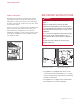
INSTALLATION Preparation Before moving the range, protect any finished flooring and secure oven door(s) closed to prevent damage. To lighten the load or to fit through a door way, the oven door(s) can be removed. Only remove if necessary. Do not remove griddle or any other component. Door removal should only be done by a certified installer or service technician. For removal, a hinge pin will be inserted into the appropriate hinge shown in the illustrations below.
INSTALLATION Placement Leveling Do not lift or carry the oven door by the door handle. The range has rear casters which allow for easy movement by lifting the front of the unit. Raise the unit to its desired height by adjusting the front legs and rear casters. Use a 3/4" socket to adjust the rear casters. The front legs can be adjusted by rotating the hexagonal leg clockwise to raise and counterclockwise to lower. Use an appliance dolly to move the unit near the opening.
INSTALLATION Anti-Tip Bracket To prevent the unit from tipping forward, the anti-tip bracket must be installed. To ensure the anti-tip bolt engages the bracket, refer to the chart and illustration below to determine proper placement. ANTI-TIP BRACKET WIDTH ANTI-TIP BOLT ADJUSTMENT Once the bracket is secure, adjust the anti-tip bolt so the top of the washer is 7/8" (22) maximum from the floor. Slide the range into the opening and verify the anti-tip bolt is engaged. Refer to the illustrations below.
INSTALLATION Electrical Connection Gas Supply Connection The terminal block on the back of the range allows for a 3-wire or 4-wire installation. For a 4-wire installation, the ground strap from the unit to the terminal block must be cut. Two concentric knockouts are provided to allow for permanent or cordset wiring of the unit. All connections to the gas piping must be wrench-tightened. Do not overtighten or allow pipes to turn when tightening.
TROUBLESHOOTING Troubleshooting IMPORTANT NOTE: If the range does not operate properly, follow these troubleshooting steps: • Verify electrical power is supplied to the range. • Verify the gas supply shut-off valve is in the open position. • If the range does not operate properly, contact Wolf factory certified service. Do not attempt to repair the range. Wolf is not responsible for service required to correct a faulty installation.
ESTUFAS DE ENERGÍA DUAL Contenido 3 Precauciones Aviso importante de seguridad 4 Especificaciones 7 Instalación Resolución de problemas 11 Las características y especificaciones están sujetas a cambios sin previo aviso. Visite wolfappliance.com/specs para obtener la información más actualizada.
PRECAUCIONES DE SEGURIDAD Información del producto La información importante del producto, incluido el modelo y número de serie de la unidad, se encuentra en la placa de datos del producto. La placa de datos se encuentra en la parte inferior del montaje del panel de control, en el extremo derecho, justo por encima de la puerta del horno. Consulte la siguiente ilustración.
ESPECIFICACIONES Requisitos de instalación Instalación eléctrica AVISO IMPORTANTE: al realizar la instalación contra una superficie combustible, se requiere una tarima con altura mínima de 10" (254) para una estufa de energía dual de 36" (914) con parrilla o plancha y para todos los modelos de 48" (1219) y 60" (1524). La instalación debe tener una conexión a tierra de conformidad con los códigos locales o, en ausencia de códigos locales, con el Código Nacional de Electricidad, ANSI/NFPA 70.
ESPECIFICACIONES Suministro de gas La instalación debe cumplir con los códigos locales o, en ausencia de códigos locales, con el Código Nacional de Gas Combustible. Localice el suministro de gas en la zona sombreada que se muestra en la ilustración de la página 6. La estufa está equipada para su uso con gas licuado (LP) o propano natural. Su diseño está certificado por la Asociación Canadiense de Normas (CSA, por sus siglas en inglés) para gas natural o LP.
ESPECIFICACIONES Estufa de energía dual INSTALACIÓN 13" (330) 30" (762) A 36" (914) A LA PARTE INFERIOR DE LA CAMPANA DE VENTILACIÓN** máx 18" (457) como mínimo 6" (152) A MATERIAL COMBUSTIBLE* 36" (914) DE PISO A MOSTRADOR 6" (152) A MATERIAL COMBUSTIBLE* ANCHURA DE ABERTURA 36 7/8" (937) A LA SUPERFICIE PARA COCINAR UBICACIÓN DE LAS EXTENSIONES DE GAS Y ELECTRICIDAD EN EL PISO 21/4" (57) A 10" (254) INSTALACIÓN DE GAS 31/4" (83) VISTA LATERAL VISTA FRONTAL 13" (330) INSTALACIÓN ELÉCTRICA
INSTALACIÓN Preparación Antes de mover la estufa, proteja cualquier suelo acabado y asegúrese de que la puerta del horno esté cerrada para que no se dañe. Puede quitar la(s) puerta(s) del horno para aligerar la carga o para pasar el horno por una puerta. Quítela únicamente si es necesario. No retire la plancha ni ninguno de los otros componentes. El proceso para quitar la puerta del horno solamente debe ser realizado por un instalador certificado o un técnico de servicio.
INSTALACIÓN Colocación Nivelación No utilice la manija de la puerta del horno para levantar la puerta ni para transportarla. La estufa tiene ruedas traseras para facilitar su desplazamiento levantando el frente de la unidad. Para levantar la unidad a la altura deseada, ajuste las patas delanteras y las ruedas traseras. Utilice una llave de 3/4" para ajustar las ruedas traseras. Las patas delanteras se pueden ajustar girando la pata hexagonal hacia la derecha para subir y hacia la izquierda para bajar.
INSTALACIÓN Soporte antivuelco Para evitar que la unidad se incline hacia delante y proporcionar una instalación estable, la unidad debe estar asegurada en su lugar con el soporte antivuelco. Para asegurarse de que el perno antivuelco se acople con el soporte, consulte el gráfico y la ilustración de abajo para determinar cómo colocarlo correctamente.
INSTALACIÓN Conexión eléctrica Conexión del suministro de gas El bloque de terminales en la parte posterior de la estufa permite una instalación de 3 cables o 4 cables. Para una instalación de 4 cables, debe cortar la banda de conexión a tierra en el bloque de terminales de la unidad. Se proporcionan dos tapas prepunzonadas concéntricas para permitir el cableado permanente o en conjunto de la unidad. Todas las conexiones a la tubería de gas deben apretarse con llave.
RESOLUCIÓN DE PROBLEMAS Resolución de problemas AVISO IMPORTANTE: si la estufa no funciona correctamente, siga estos pasos para resolver los problemas: • Compruebe que la estufa tiene corriente eléctrica. • Compruebe que la llave de paso del suministro de gas se encuentra en posición abierta. • Si la estufa no funciona correctamente, póngase en contacto con el centro de servicio autorizado de Wolf. No intente reparar la estufa.
CUISINIÈRES MIXTES Table des matières Remarque importante 3 Précautions Pour s’assurer que ce produit est installé et utilisé en toute sécurité et aussi efficacement que possible, prenez note des types de renseignement mis en évidence tout au long de ce guide : de sécurité 4 Spécifications 7 Installation Dépannage 11 REMARQUE IMPORTANTE met en évidence des renseignements qui sont particulièrement importants.
PRÉCAUTIONS DE SÉCURITÉ Renseignements sur le produit Des renseignements importants sur le produit, y compris les numéros de modèle et de série, se trouvent sur la plaque signalétique du produit. La plaque signalétique est située au fond de l’assemblage du panneau de contrôle à l’extrême droite, juste au-dessus de la porte du four. Reportez-vous à l’illustration ci-dessous. Si vous avez besoin de service, communiquez avec le service Wolf certifié par l’usine avec les numéros de modèle et de série.
SPÉCIFICATIONS Exigences d’installation Électricité REMARQUE IMPORTANTE : lorsque vous effectuez L’installation doit être mise à la terre électriquement conformément aux codes locaux ou, en l’absence de codes locaux, au code national de l’électricité, ANSI/NFPA 70.
SPÉCIFICATIONS Alimentation en gaz L’installation doit se conformer aux codes locaux ou, en l’absence de codes locaux, au code national relatif au gaz combustible. Repérez l’alimentation en gaz dans la zone ombragée indiquée dans l’illustration à la page 6. La cuisinière est configurée pour être utilisée avec du gaz naturel ou de pétrole liquéfié (PL). Sa conception est certifiée par l’Association canadienne de normalisation (ACNOR) pour le gaz naturel et le gaz de pétrole liquéfié.
SPÉCIFICATIONS Cuisinière mixte INSTALLATION 13 po (330) 30 PO (762) À 36 PO (914) max. JUSQU’AU BAS DE LA HOTTE** 18 po (457) min.
INSTALLATION Préparation Avant de déplacer la cuisinière, protégez tout plancher fini et fixez la (les) porte(s) du four en position fermée pour éviter tout dommage. Pour alléger la charge ou pour passer à travers une entrée de porte, la (les) porte(s) du four peut (peuvent) être enlevée(s). Procédez au retrait seulement si cela est nécessaire. Ne retirez pas la plaque à frire ou tout autre composant. Le retrait de la porte doit être effectué par un technicien de service ou un installateur qualifiés.
INSTALLATION Mise en place Nivellement Ne soulevez pas et ne transportez pas la porte du four par la poignée. La cuisinière possède des roulettes arrière qui facilitent le mouvement en soulevant le devant de l’unité. Soulevez l’unité jusqu’à la hauteur désirée en réglant les pieds avant et les roulettes arrière. Utilisez une douille de 3/4 po pour régler les roulettes arrière.
INSTALLATION Support antibasculement Pour empêcher l’unité de basculer vers l’avant et obtenir une installation stable, elle doit être fixée en place au moyen le support antibasculement. Pour s’assurer que le boulon antibasculement enclenche le support, reportez-vous au tableau et à l’illustration ci-dessous pour déterminer l’emplacement approprié.
INSTALLATION Connexion électrique Connexion de l’alimentation en gaz Le bloc de branchement situé à l’arrière de la cuisinière permet une installation à trois ou quatre fils. Pour une installation à quatre fils, la tresse de masse allant de l’unité au bloc de branchement doit être coupée. Deux alvéoles défonçables concentriques sont fournies pour permettre le câblage permanent ou amovible de l’unité. Toutes les connexions vers le tuyau de gaz doivent être serrées au moyen d’une clé.
DÉPANNAGE Dépannage REMARQUE IMPORTANTE : si la cuisnière ne fonctionne pas correctement, suivez les étapes de dépannage suivantes : • Vérifiez que la cuisinière est alimentée en électricité. • Assurez-vous que le robinet d’arrêt d’alimentation de gaz se trouve en position ouverte. • Si la cuisinière ne fonctionne pas correctement, communiquez avec le centre service Wolf certifié par l’usine. Ne tentez pas de réparer la cuisinière.
WOLF APPLIANCE, INC. P.O. BOX 44848 MADISON, WI 53744 822583 REV-B WOLFAPPLIANCE.COM 7 / 2014 800.222.