Dual Fuel Ranges Installation Guide
DUAL FUEL RANGES Contents Important Note 3 Safety To ensure the safe and efficient installation of Wolf equipment, please take note of the following types of highlighted information throughout this guide: Precautions 4 Specifications 7 Installation Troubleshooting 11 IMPORTANT NOTE highlights information that is especially relevant to a problem-free installation. CAUTION signals a situation where minor injury or product damage may occur if instructions are not followed.
SAFETY PRECAUTIONS Product Information Important product information including the model and serial number are listed on the product rating plate. The rating plate is located on the bottom of the control panel assembly, at the far right, just above the oven door. Refer to the illustration below. If service is necessary, contact Wolf factory certified service with the model and serial number.
SPECIFICATIONS Installation Requirements Electrical IMPORTANT NOTE: When installing against a combustible surface, a minimum 10" (254) riser is required for a 36" (914) dual fuel range with charbroiler or griddle and all 48" (1219) and 60" (1524) models. Installation must comply with all applicable electrical codes. Locate the electrical supply flush with the wall or floor and within the shaded area shown in the illustration on page 6.
SPECIFICATIONS Gas Supply Installation must conform with local codes or, in the absence of local codes, with the National Fuel Gas Code. Locate the gas supply within the shaded area shown in the illustration on page 6. The range is equipped for use with natural or liquid propane (LP) gas. It is design certified by the Canadian Standards Association (CSA) for natural or LP gases. The product rating plate has information on the type of gas that should be used.
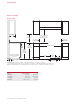
SPECIFICATIONS Dual Fuel Range INSTALLATION 13" (330) 30" (762) TO 36" (914) max TO BOTTOM OF VENTILATION HOOD** 18" (457) min 6" (152) TO COMBUSTIBLE* 6" (152) TO COMBUSTIBLE* 36" (914) FLOOR TO COUNTERTOP OPENING WIDTH 36 7/8" (937) TO COOKING SURFACE LOCATION OF GAS AND ELECTRICAL EXTENDS ON FLOOR 21/4" (57) A 10" (254) GAS 31/4" (83) SIDE VIEW FRONT VIEW 13" (330) ELECTRICAL *Minimum clearance from rough opening to combustible materials up to 18" (457) above countertop.
INSTALLATION Preparation Before moving the range, protect any finished flooring and secure oven door(s) closed to prevent damage. To lighten the load or to fit through a door way, the oven door(s) can be removed. Only remove if necessary. Do not remove griddle or any other component. Door removal should only be done by a certified installer or service technician. For removal, a hinge pin will be inserted into the appropriate hinge shown in the illustrations below.
INSTALLATION Placement Anti-Tip Bracket Do not lift or carry the oven door by the door handle. The range has rear casters which allow for easy movement by lifting the front of the unit. Raise the unit to its desired height by adjusting the front legs and rear casters. Use a 3/4" socket to adjust the rear casters. The front legs can be adjusted by rotating the hexagonal leg clockwise to raise and counterclockwise to lower. Use an appliance dolly to move the unit near the opening.
INSTALLATION Anti-Tip Bracket INSTALL BRACKET ANTI-TIP BOLT ADJUSTMENT Drywall application | After properly positioning the anti-tip bracket, mark holes, then use a Philips screwdriver or a low rpm power drill to drive the wall anchor into the surface of the wallboard until flush. Pre-drill holes if needed. For hard wallboard or double-board construction, use a 1/4" drill bit. For solid plaster, use a 7/16" drill bit. Refer to the illustration below.
INSTALLATION Electrical Connection Gas Supply Connection The terminal block on the back of the range allows for a 3-wire or 4-wire installation. For a 4-wire installation, the ground strap from the unit to the terminal block must be cut. Two concentric knockouts are provided to allow for permanent or cordset wiring of the unit. All connections to the gas piping must be wrench-tightened. Do not overtighten or allow pipes to turn when tightening.
TROUBLESHOOTING Troubleshooting IMPORTANT NOTE: If the range does not operate properly, follow these troubleshooting steps: • Verify electrical power is supplied to the range. • Verify the gas supply shut-off valve is in the open position. • If the range does not operate properly, contact Wolf factory certified service. Do not attempt to repair the range. Wolf is not responsible for service required to correct a faulty installation.
WOLF APPLIANCE, INC. P.O. BOX 44848 MADISON, WI 53744 822583 REV-A WOLFAPPLIANCE.COM 4 / 2013 800.222.