
Design Guide


wolfappliance.com | 93
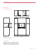
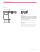
21" (533)
BEHIND FRAME
5
1
/2"
(140)
7
/8"
(22)
DRAWER
FULL EXTENSION
19"
(483)
23
1
/2" (597)
Cup Warming Drawer
DIMENSIONS
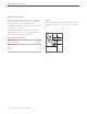
Planning Information
The Cup Warming Drawer can be installed in a standard
or flush inset application. Finish the edges of the opening.
They may be visible when the drawer is open.
For standard installations, the face trim will overlap stiles
and rails. Refer to the chart below.
For flush inset installations, a minimum ⁄"
(3) reveal is
required on all sides. To ensure consistent reveals, each
corner of the opening must be exactly 90°.
INSTALLATION REQUIREMENTS
BASE SUPPORT MIN
Cup Warming Drawer 75 lb (34 kg)
TRIM OVERLAP
Top 0" (0)
Bottom 0" (0)
Sides ⁄" (18)
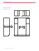
COMBINATION INSTALLATION
To install a Cup Warming Drawer below a Coee System,
one opening for both units must be specified. To achieve
the minimum reveal between the units, place the Coee
System support rails on top of the Cup Warming Drawer,
then secure the rails to the sides of the cabinet. Any mate-
rial between the units will increase the horizontal reveal.
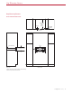
ELECTRICAL REQUIREMENTS
Installation must comply with all applicable electrical codes.
Locate the electrical supply as shown in the illustrations
on the following pages. A separate circuit servicing only
this appliance is required. A ground fault circuit interrupter
(GFCI) is not recommended and may cause interruption of
operation.
ELECTRICAL REQUIREMENTS
Electrical Supply grounded, 120 VAC, 60 Hz
Service 10 amp dedicated circuit
Receptacle 3-prong grounding-type
Power Cord 3' (.9 m)
Cup Warming Drawer