WARMING DRAWER INSTALLATION INSTRUCTIONS CAJÓN CALENTADOR INSTRUCCIONES DE INSTALACIÓN TIROIR CHAUFFANT INSTRUCTIONS D’INSTALLATION CASSETTO SCALDAVIVANDE ISTRUZIONI PER L’INSTALLAZIONE INSTALLATIONSANWEISUNGEN
ENGLISH 4 ESPÃNOL 22 FRANÇAIS 40 I TA L I A N O 58 DEUTSCH 76 3
C O N TA C T I N F O R M AT I O N Website: wolfappliance.com As you follow these instructions, you will notice WARNING and CAUTION symbols. This blocked information is important for the safe and efficient installation of Wolf equipment. There are two types of potential hazards that may occur during installation. signals a situation where minor injury or product damage may occur if you do not follow instructions. states a hazard that may cause serious injury or death if precautions are not followed.
W O L F WA R M I N G D R AW E R I N S TA L L AT I O N R E Q U I R E M E N T S IMPORTANT NOTE: This installation must be completed by a qualified technician. Installer: Please read the entire Installation Instructions prior to installation. Save these instructions for the local inspector’s reference, then leave them with the homeowner. Homeowner: Please read and keep these instructions for future reference and be sure to read the entire Use & Care Information prior to use.
W O L F WA R M I N G D R AW E R B E F O R E Y O U S TA R T Before you install the warming drawer, make sure you have the Wolf accessory drawer front called for in your installation. ACCESSORIES Optional accessories are available through your Wolf dealer. IMPORTANT NOTE: If you are installing the warming drawer with integrated drawer front in an inset panel application, make sure that your cabinetry meets the minimum 838 mm width and 635 mm depth requirement for this installation.
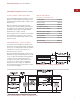
I N S TA L L AT I O N I N S T R U C T I O N S S TA I N L E S S S T E E L D R A W E R F R O N T I N S TA L L AT I O N S P E C I F I C AT I O N S The following illustrations provide the overall dimensions and installation specifications for the Wolf warming drawer with a stainless steel drawer front. Wolf recommends using a 838 mm wide cabinet for the warming drawer with stainless steel drawer front. A minimum 762 mm wide by 610 mm deep cabinet is required with a minimum base support of 91 kg.
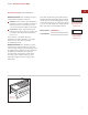
W O L F WA R M I N G D R AW E R S TA I N L E S S S T E E L D R A W E R F R O N T I N S TA L L AT I O N W I T H B U I LT- I N O V E N The Wolf warming drawer with stainless steel drawer front may be installed below or above a Wolf 762 mm built-in single oven or below a double oven, provided the warming drawer is fully enclosed, top and bottom. Refer to the illustration below. Also refer to installation instructions provided with the built-in oven for additional specifications.
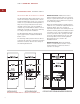
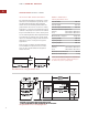
I N S TA L L AT I O N I N S T R U C T I O N S S TA I N L E S S S T E E L D R A W E R F R O N T O P T I O N A L I N S TA L L AT I O N S The Wolf warming drawer with stainless steel drawer front may be installed in combination with a 762 mm single oven and microwave oven with 762 mm trim, provided the warming drawer is fully enclosed, top and bottom. Refer to the illustration below. Also refer to installation instructions provided with the built-in oven and microwave for additional specifications.
W O L F WA R M I N G D R AW E R I N T E G R AT E D D R A W E R F R O N T I N S TA L L AT I O N S P E C I F I C AT I O N S The following illustrations provide the overall dimensions and installation specifications for the Wolf warming drawer with integrated drawer front. The warming drawer with integrated drawer front can be used in an overlay application or an inset panel application where it will be completely recessed in to the cabinet.
I N S TA L L AT I O N I N S T R U C T I O N S I N T E G R AT E D D R A W E R F R O N T O V E R L AY A P P L I C AT I O N U N D E R C O U N T E R I N S TA L L AT I O N A minimum 838 mm wide by 610 mm deep cabinet is required for the warming drawer with integrated drawer front using the overlay application. A minimum base support of 91 kg is required. Refer to the illustration on page 10. For undercounter installations, 597mm from the bottom of the warming drawer opening to the floor is recommended.
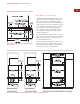
W O L F WA R M I N G D R AW E R I N T E G R AT E D D R A W E R F R O N T I N S TA L L AT I O N W I T H B U I LT- I N O V E N The Wolf warming drawer with integrated drawer front may be installed below or above a Wolf 762 mm or 914 mm built-in single oven, provided the warming drawer is fully enclosed, top and bottom. Refer to the illustration below. Also refer to installation instructions provided with the built-in oven for additional specifications.
I N S TA L L AT I O N I N S T R U C T I O N S I N T E G R AT E D D R A W E R F R O N T I N S TA L L AT I O N O P T I O N S The Wolf warming drawer with integrated drawer front may be installed in combination with a 762 mm single built-in oven and microwave with 762 mm trim, provided the warming drawer is fully enclosed, top and bottom. Refer to the illustration below.
W O L F WA R M I N G D R AW E R ELECTRICAL R E Q U I R E M E N T S I M P O R TA N T N OT E You must follow all local codes and ordinances when installing your service. The Wolf warming drawer requires a separate, grounded 220 – 240 V AC, 50/60 Hz power supply and must be connected to an individual properly grounded branch circuit and protected by a 15 or 20 amp circuit breaker or time delay fuse.
I N S TA L L AT I O N I N S T R U C T I O N S C A B I N E T S U P P O RT S U N PA C K T H E W A R M I N G D R A W E R IMPORTANT NOTE: When the warming drawer is installed with a built-in oven, additional clearance between openings may be required. Check that oven supports do not obstruct the interior dimensions required for the warming drawer. Unpack the warming drawer on a flat surface. Remove all packaging materials and tape from inside the warming drawer and discard.
W O L F WA R M I N G D R AW E R S TA I N L E S S S T E E L F R O N T P A N E L I N S TA L L A N T I - T I P B L O C K I N G An anti-tip block or platform must be installed to prevent the warming drawer from tipping forward while opened when loaded. Failure to do so could result in personal injury and damage to the cabinet. Install a 51 mm x 51 mm or 51 mm x 102 mm anti-tip block against the rear cabinet wall.
I N S TA L L AT I O N I N S T R U C T I O N S S TA I N L E S S S T E E L F R O N T P A N E L I N S TA L L F R O N T P A N E L I N S TA L L W A R M I N G D R A W E R Remove all packaging materials from the handle and front panel. Gently remove the protective covering from the stainless steel front panel. The adhesive covering should peel away from the surface cleanly, but any remaining residue should be cleaned off with a mild detergent. Slide the left corner of the warming drawer into the opening.
W O L F WA R M I N G D R AW E R I N T E G R AT E D F R O N T P A N E L I N S TA L L C L E AT S A N D P L AT F O R M For an overlay or inset application, you will need to install a recessed platform and cleats of the following dimensions into the opening. Top Cleat Dimensions 749 mm W x 13 mm H x 51 mm D Side Cleat Dimensions 13 mm W x 232 mm H x 51 mm D IMPORTANT NOTE: Be sure to finish the inside lip of the opening and the front face of the shelf and cleats.
I N S TA L L AT I O N I N S T R U C T I O N S I N T E G R AT E D F R O N T P A N E L I N S TA L L A N T I - T I P B L O C K I N G I N S TA L L W A R M I N G D R A W E R Install a 51 mm x 51 mm or 51 mm x 102 mm anti-tip block against the rear cabinet wall as shown in the installation illustration for your specific installation on pages 11–13. Turn power off to the electrical outlet. Slide the left corner of the warming drawer into the opening.
W O L F WA R M I N G D R AW E R I N T E G R AT E D F R O N T P A N E L I N S TA L L F R O N T P A N E L T O D R A W E R Disconnect the communications line from communications jack. The communications jack is removed by depressing retaining clip from front of mounting panel, then pushing the retaining clip side of jack through mounting panel first, then pivoting jack out of mounting panel. Place removed communications jack inside drawer frame assembly.
I N S TA L L AT I O N I N S T R U C T I O N S TROUBLES H O OT I N G IMPORTANT NOTE: If the warming drawer does not operate properly, follow these troubleshooting steps: Verify that power is being supplied to the warming drawer. Check electrical connections to ensure that the installation has been completed correctly. Refer to the Troubleshooting Guide in the Wolf Warming Drawer Use & Care Information.
INFORMACIÓN D E C O N TA C T O Página Web: wolfappliance.com A medida que siga las instrucciones que aparecen en esta guía, encontrará símbolos de ADVERTENCIA y PRECAUCIÓN. Esta información en recuadros es importante para instalar el equipo de Wolf de forma segura y eficaz. Existen dos tipos de posibles riesgos que pueden producirse durante una instalación. indica una situación en la que pueden producirse heridas personales leves o daños secundarios en el producto si no se siguen las instrucciones.
C A J Ó N C A L E N TA D O R D E WO L F R E Q U I S I TO S D E I N S T A L A C I Ó N NOTA IMPORTANTE: Esta instalación debe ser realizada por un técnico cualificado. Instalador: Lea las instrucciones de instalación antes de llevar a cabo la instalación. Guarde estas instrucciones para que el inspector local pueda utilizarlas como refe-rencia y, a continuación, entréguelas al propietario del aparato.
C A J Ó N C A L E N TA D O R D E WO L F ANTES D E C O M E N Z A R Antes de instalar el cajón calentador, asegúrese de que tiene preparado el frente de cajón de Wolf para que sea instalado. ACCESORIOS Podrá disponer de los accesorios opcionales en el distribuidor de Wolf correspondiente. NOTA IMPORTANTE: Si está instalando el cajón calentador con el frente integrado para un uso empotrado, asegúrese de que el mobiliario cumple las medidas mínimas de 838 mm de ancho y 635 mm de fondo.
I N S T R U C C I O N E S D E I N S TA L A C I Ó N F R E N T E D E C A J Ó N D E ACERO I N OX I DA B L E ESPECIFIC ACIONES DE LA I N S TA L A C I Ó N MODELO ICBWWD30 La siguiente ilustración proporciona las medidas totales y las especificaciones de la instalación para el cajón calentador de Wolf con el frente de acero inoxidable.
C A J Ó N C A L E N TA D O R D E WO L F F R E N T E D E C A J Ó N D E ACERO I N OX I DA B L E I N S TA L A C I Ó N C O N H O R N O INTEGRABLE El cajón calentador de Wolf con frente de acero inoxidable puede instalarse debajo de o sobre un horno sencillo integrable de 762 mm o debajo de un horno doble siempre que el cajón calentador quede completamente ajustado en la parte superior e inferior. Observe la siguiente ilustración.
I N S T R U C C I O N E S D E I N S TA L A C I Ó N FRENTE DE CAJÓN DE ACERO INOXIDABLE I N S TA L A C I O N E S O P C I O N A L E S El cajón calentador de Wolf con frente de acero inoxidable puede instalarse en combinación con un horno sencillo de 762 mm y con un microondas con un borde de 762 mm siempre que el cajón calentador quede completamente ajustado a la parte superior e inferior. Observe la siguiente ilustración.
C A J Ó N C A L E N TA D O R D E WO L F F R E N T E D E C A J Ó N INTEGRADO ESPECIFIC ACIONES DE LA I N S TA L A C I Ó N MODELO ICBWWD30 Las siguientes ilustraciones proporcionan las medidas generales y las especificaciones de la instalación para el cajón calentador de Wolf con frente de acero inoxidable. El cajón calentador con frente integrado se puede utilizar en aplicaciones empotradas o revestible, por lo que el cajón quedará completamente acoplado en el mueble.
I N S T R U C C I O N E S D E I N S TA L A C I Ó N FRENTE DE CAJÓN INTEGRADO APLIC ACIÓN REVESTIBLE I N S TA L A C I Ó N B A J O E N C I M E R A Se requiere un mueble con un ancho de 838 mm por un fondo de 610 mm mínimo para el cajón calentador con frente integrado si es una instalación revestible. Se requiere un soporte de base que aguante un peso de 91 kg mínimo. Consulte la ilustración de la página 28.
C A J Ó N C A L E N TA D O R D E WO L F FRENTE DE CAJÓN INTEGRADO I N S TA L A C I Ó N C O N H O R N O INTEGRABLE El cajón calentador de Wolf con frente integrado puede instalarse debajo o encima de un horno integrable Wolf de 762 mm ó 914 mm siempre que el cajón calentador quede completamente ajustado al cerrarse, tanto en la parte inferior como en la parte superior. Observe la siguiente ilustración.
I N S T R U C C I O N E S D E I N S TA L A C I Ó N FRENTE DE CAJÓN INTEGRADO O P C I O N E S D E I N S TA L A C I Ó N El cajón calentador de Wolf con frente de cajón integrado puede instalarse en combinación con un horno sencillo de 762 mm y con un microondas que tenga un borde de 762 mm siempre que el cajón calentador quede completamente ajustado al cerrarse tanto en la parte superior como en la inferior. Observe la siguiente ilustración.
C A J Ó N C A L E N TA D O R D E WO L F R E Q U I S I TO S ELÉCTRICOS El cajón calentador de Wolf debe ser conectado a una red eléctrica individual con toma a tierra de 220 – 240 V CA, 50/60 Hz, 2500 w y con un fusible protector de 15 amperios. N O TA I M P O R TA N T E : NOTA IMPORTANTE: El cajón calentador debe ser conectado a una base enchufe monofásica con toma a tierra. Deberá cumplir todas las ordenanzas y normativas nacionales cuando instale el aparato.
I N S T R U C C I O N E S D E I N S TA L A C I Ó N S O P O RT E S D E L O S M U E B L E S DESEMBALAJE DEL CAJÓN C A L E N TA D O R NOTA IMPORTANTE: Cuando el cajón calentador se instale con un horno integrable, necesitará dejar un espacio adicional entre las dos cavidades. Compruebe que los soportes del horno no obstruyen las medidas interiores requeridas para el cajón calentador. Desembale el cajón calentador en una superficie plana.
C A J Ó N C A L E N TA D O R D E WO L F P A N E L F R O N TA L D E A C E R O I N OX I DA B L E I N S TA L A C I Ó N D E L B O R D E D E L C A J Ó N C A L E N TA D O R I N S TA L A C I Ó N D E L B L O Q U E ANTI-VUELCO Retire todos los materiales de embalaje del borde. El kit del frente de acero inoxidable incluye dos bordes largos para el anillo inferior y superior del cajón calentador y dos bordes cortos para los laterales. Cada borde tiene una ranura que encaja en el borde del anillo.
I N S T R U C C I O N E S D E I N S TA L A C I Ó N P A N E L F R O N TA L D E A C E R O I N OX I DA B L E I N S TA L A C I Ó N D E L P A N E L F R O N TA L Retire todos los materiales del embalaje del tirador y del panel frontal. Retire con cuidado la cubierta protectora del panel frontal de acero inoxidable. Debe retirar la cubierta adhesiva de la superficie y limpiar cualquier residuo que quede con detergente suave.
C A J Ó N C A L E N TA D O R D E W O L F PA N E L F R O N TA L I N T E G R A D O I N S TA L A C I Ó N D E L O S L I S T O N E S Y D E L A P L ATA F O R M A Tanto para una instalación revestible como para una instalación empotrada, necesitará instalar una plataforma y unos listones con las siguientes dimensiones. Dimensiones del listón superior 749 mm A x 13 mm Alto x 51 mm F NOTA IMPORTANTE: Asegúrese de pulir el borde interior de la apertura y la parte delantera del estante y de los listones.
I N S T R U C C I O N E S D E I N S TA L A C I Ó N P A N E L F R O N TA L I N T E G R A D O I N S TA L A C I Ó N D E L C A J Ó N C A L E N TA D O R I N S TA L A C I Ó N D E L B L O Q U E A N T I VUELCO Desconecte el aparato de la red eléctrica. Introduzca la esquina izquierda del cajón calentador por la apertura. Si la toma de corriente se instala dentro de la cavidad, enchufe el cable de alimentación en la toma. El cable que sobre debe enrollarse por detrás o al lado de la unidad.
C A J Ó N C A L E N TA D O R D E WO L F P A N E L F R O N TA L I N T E G R A D O I N S TA L A C I Ó N D E L P A N E L F R O N TA L EN EL CAJÓN Desconecte la línea de comunicaciones del enchufe para comunicaciones.
I N S T R U C C I O N E S D E I N S TA L A C I Ó N S O L U C I Ó N D E PROBLEMAS S I N E C E S I TA A S I S T E N C I A TÉCNICA NOTA IMPORTANTE: Si el cajón calentador no funciona correctamente, siga estos pasos de localización y solución de problemas: Compruebe que el cajón calentador está conectado al suministro eléctrico. Compruebe las conexiones eléctricas para asegurarse de que la instalación se ha llevado a cabo de manera correcta.
I N F O R M AT I O N D E C O N TA C T Site Internet : wolfappliance.com Vous remarquerez tout au long de ce manuel d’instructions les mentions AVERTISSEMENT et MISE EN GARDE, destinées à fournir des recommandations importantes afin d’assurer la sécurité et l’efficacité de l’installation de l’équipement Wolf. Deux types de dangers potentiels peuvent se présenter pendant l’ins-tallation.
T I R O I R C H A U F FA N T WOLF E X I G E N C E S R E L AT I V E S A L’ I N S TA L L AT I O N REMARQUE IMPORTANTE : L’installation doit être effectuée par un poseur qualifié. Poseur : Veuillez lire les instructions d’installation dans leur intégralité avant de procéder à l’installation. Veuillez conserver ces instructions afin que le technicien local puisse s’y reporter, puis laissez-les au propriétaire.
T I R O I R C H A U F FA N T WOLF AVA N T D E C O M M E N C E R Avant d’installer le tiroir chauffant, assurezvous de disposer de l’accessoire de façade de tiroir Wolf requis pour l’installation voulue. ACCESSOIRES Des accessoires sont proposés en option chez votre dépositaire Wolf.
I N S T RU C T I O N S D ’ I N S TA L L AT I O N FAC A D E D E T I RO I R EN ACIER I N OX Y DA B L E S P E C I F I C AT I O N S D ’ I N S TA L L AT I O N MODELE ICBWWD30 Les illustrations ci-après fournissent les dimensions hors-tout et les spécifications d’installation du tiroir chauffant Wolf équipé d'une façade en acier inoxydable. façade en acier inoxydable Wolf recommande d’utiliser un élément de cuisine de 838 mm de largeur pour installer le tiroir chauffant avec façade en acier inoxydable.
T I R O I R C H A U F F A N T WO L F FAC A D E D E T I RO I R EN ACIER I N OX Y DA B L E I N S TA L L AT I O N A V E C F O U R E N C A S T R E Le tiroir chauffant Wolf avec façade en acier inoxydable peut être installé au-dessous ou audessus d’un four encastré simple de 762 mm ou au-dessous d’un four double Wolf, à condition qu’il soit complètement enfermé, haut et bas. Reportez-vous à l’illustration ci-après.
I N S T R U C T I O N D ’ I N S TA L L AT I O N FAC A D E D E T I RO I R EN ACIER I N OX Y DA B L E O P T I O N S D ’ I N S TA L L AT I O N Le tiroir chauffant Wolf équipé d’une façade en acier inoxydable peut être installé combiné à un four simple et à un four micro-ondes de 762 mm avec une moulure de 762 mm, à condition qu’il soit complètement enfermé, haut et bas. Reportez-vous à l’illustration ciaprès.
T I R O I R C H A U F FA N T W O L F FAC A D E D E T I RO I R INTEGREE S P E C I F I C AT I O N S D ’ I N S TA L L AT I O N Les illustrations ci-après fournissent les dimensions hors-tout et les spécifications d’installation du tiroir chauffant Wolf avec façade intégrée. Le tiroir chauffant avec façade intégrée peut être utilisé habillé d’un panneau épais ou d’affleurement qui lui permettra d’être complètement encastré dans l’élément de cuisine.
I N S T R U C T I O N S D ’ I N S TA L L AT I O N FAC A D E D E T I RO I R INTEGREE HABILLABLE Un élément de cuisine de 838 mm de large et de 610 mm de profondeur (exigences minimales) est requis pour l’installation d’une façade de tiroir intégrée, ainsi qu’un appui de base pouvant supporter une charge minimale de 91 kg. Reportez-vous à l’illustration page 46.
T I R O I R C H A U F FA N T W O L F FAC A D E D E T I R O I R I N T E G R E E I N S TA L L AT I O N A V E C F O U R ENCASTRE Le tiroir chauffant Wolf avec façade intégrée peut être installé au-dessous ou au-dessus d’un four encastré simple Wolf de 762 mm ou de 914 mm, à condition qu’il soit complètement enfermé, haut et bas. Reportez-vous à l’illustration ci-après. Reportez-vous également aux instructions d’installation fournies avec le four encastré pour obtenir des spécifications supplémentaires.
I N S T R U C T I O N S D ’ I N S TA L L AT I O N FAC A D E D E T I R O I R I N T E G R E E O P T I O N S D ’ I N S TA L L AT I O N Le tiroir chauffant Wolf avec une façade intégrée peut être installé combiné à un four simple et à un four micro-ondes encastrés de 762 mm avec une moulure de 762 mm, à condition qu’il soit complètement enfermé, haut et bas. Reportez-vous à l’illustration ci-après.
T I R O I R C H A U F FA N T W O L F C O N F I G U R AT I O N E L E C T R I Q U E REMARQUE I M P O R TA N T E Conformez-vous aux ordonnances et aux codes locaux lorsque vous installez votre alimentation électrique. Le tiroir chauffant Wolf exige une alimentation électrique distincte et mise à la terre de 220 – 240 V c.a. et de 50/60 Hz et doit être raccordé à un circuit de dérivation individuel correctement mis à la terre et protégé par un disjoncteur ou un fusible temporisé de 15 ou 20 A.
I N S T R U C T I O N S D ’ I N S TA L L AT I O N A P P U I S D’ELEMENT DE CUISINE DEBALLAGE D U T I RO I R C H A U F FA N T REMARQUE IMPORTANTE : Lorsque le tiroir chauffant est installé avec un four encastré, un espace supplémentaire entre les ouvertures pourrait se révéler nécessaire. Assurez-vous que les appuis du four n’empiètent pas sur les dimensions intérieures requises pour le tiroir chauffant. Déballez le tiroir chauffant sur une surface plane.
T I R O I R C H A U F FA N T W O L F FAC A D E D E T I RO I R EN ACIER I N OX Y DA B L E I N S TA L L AT I O N D U S Y S T E M E ANTIBASCULEMENT Un système ou une plate-forme antibasculement doit être installée pour empêcher le tiroir chauffant de basculer vers l’avant lorsque vous l’ouvrez alors qu’il est chargé. Le non-respect de cette recommandation peut entraîner des blessures et des dommages de l’élément de cuisine.
I N S T R U C T I O N S D ’ I N S TA L L AT I O N FAC A D E D E T I RO I R EN ACIER I N OX Y DA B L E I N S TA L L AT I O N D E L A F A C A D E Dégagez la poignée et la façade de tous les matériaux d’emballage. Enlevez avec précaution le revêtement de protection de la façade en acier inoxydable. Le revêtement adhésif devrait se décoller proprement de la surface, mais le cas échéant, tous résidus restants devraient être enlevés avec un détergent doux.
T I R O I R C H A U F FA N T W O L F FAC A D E D E T I RO I R INTÉGRÉE I N S TA L L AT I O N D E S TA S S E A U X E T D E L A P L AT E - F O R M E Pour une installation de tiroir habillé épais ou d’affleurement, vous devrez installer dans l’ouverture une plate-forme et des tasseaux encastrés aux dimensions suivantes : Dimensions du tasseau supérieur 749 mm L x 13 mm H x 51 mm P Dimensions des tasseaux latéraux 13 mm L x 232 mm H x 51 mm P REMARQUE IMPORTANTE : Assurez-vous de procéder à la finition de la
I N S T R U C T I O N S D ’ I N S TA L L AT I O N FAC A D E D E T I RO I R INTÉGRÉE I N S TA L L AT I O N D U S Y S T E M E ANTIBASCULEMENT I N S TA L L AT I O N D U T I R O I R C H AU F FA N T Installez un système antibasculement de 51 mm x 51 mm ou de 51 mm x 102 mm contre la paroi arrière de l’élément de cuisine tel qu’illustré pour votre installation spécifique pages 47 – 49. Coupez le courant à la prise électrique. Faites glisser le coin gauche du tiroir chauffant dans l’ouverture.
T I R O I R C H A U F FA N T W O L F FAC A D E D E T I RO I R INTÉGRÉE I N S TA L L AT I O N D E L A F A C A D E S U R L E T I RO I R Débranchez la ligne de communications de la prise de télécommunications double. Pour retirer celle-ci, abaissez l'agrafe de retenue de la façade du panneau de montage, poussez d'abord le côté de la bague de retenue de la prise à travers le panneau, puis faites pivoter la prise hors du panneau de montage. Placez la prise de télécommunications dans le cadre du tiroir.
I N S T R U C T I O N S D ’ I N S TA L L AT I O N D E P I S TA G E D E S PA N N E S REMARQUE IMPORTANTE : Si le tiroir chauffant ne fonctionne pas correctement, suivez les étapes de dépistage des pannes suivantes : Vérifiez si l’alimentation électrique est raccordée au tiroir chauffant. Vérifiez les branchements électriques afin de vous assurer que l’installation a été effectuée correctement.
INFORMAZIONI P E R I C O N TAT T I Sito Web: wolfappliance.com Man mano che seguite queste istruzioni, noterete dei simboli di AVVERTENZA ed ATTENZIONE. Queste informazioni evidenziate sono importanti per l’installazione sicura ed efficiente dell’apparecchiatura Wolf. Durante l’installazione sarete esposti a due potenziali pericoli. Segnala una situazione con possibili lesioni minori o danni al prodotto qualora non non ci si attenga a queste istruzioni.
C A S S E T T O S C A L D A V I V A N D E WO L F R E Q U I S I T I P E R L’ I N S TA L L A Z I O N E NOTA IMPORTANTE: questa installazione deve essere completata da un tecnico qualificato. Installatore: leggere tutte le istruzioni per l’installazione prima di procedere. Conservare queste istruzioni come riferimento per l’ispettore locale, quindi lasciarle al proprietario dell’abitazione.
C A S S E T TO S C A L D AV I VA N D E W O L F P R I M A DI INIZIARE Prima di installare il cassetto scaldavivande, accertarsi di disporre della mascherina Wolf giusta. ACCESSORI Gli accessori opzionali sono disponibili attraverso il rivenditore Wolf.
I S T R U Z I O N I P E R L’ I N S TA L L A Z I O N E M A S C H E R I N A A N T E R I O R E IN ACC I A I O I N O S S I DA B I L E S P E C I F I C H E P E R L ’ I N S TA L L A Z I O N E Le seguenti illustrazioni indicano le dimensioni generali e le specifiche per l’installazione del cassetto scaldavivande Wolf con una mascherina anteriore in acciaio inossidabile. Wolf consiglia di usare un mobile da 838 mm di larghezza per il cassetto scandavivande con mascherina anteriore in acciaio inossidabile.
C A S S E T TO S C A L D AV I VA N D E W O L F MASCHERINA ANTERIORE I N ACC I A I O I N O S S I DA B I L E I N S TA L L A Z I O N E C O N F O R N O I N C A S S AT O NOTA IMPORTANTE: potrebbe essere necessario più spazio tra il cassetto scaldavivande e gli incassi per i forni. Controllare che i supporti dei forni non ostruiscano le dimensioni interne richieste per il cassetto scaldavivande. Il cassetto scaldavivande Wolf è concepito ed approvato per l’installazione con forni incassati Wolf.
I S T R U Z I O N I P E R L’ I N S TA L L A Z I O N E MASCHERINA ANTERIORE I N ACC I A I O I N O S S I DA B I L E I N S TA L L A Z I O N I O P Z I O N A L I INCASSO FORNO LA GUARNIZIONE DEL FORNO FUORIESCE SOTTO LA PIATTAFORMA 3 mm BLOCCO 19 mm PIATTAFORMA DI ANTIRIBAL- SUPPORTO FORNO CON TAMENTO PARETE SPESSA GUIDA ESTERNA 63,5 mm x 63,5 mm 16 mm 273 mm INCASSO 232 mm CASSETTO SCALDAVIVANDE 600 mm 41 mm SEZIONE ESPOSTA 60 mm 260 mm PARTE 16 mm ANTERIORE VISTA LATERALE Installazione con forno i
C A S S E T TO S C A L D AV I VA N D E W O L F MASCHERINA ANTERIORE I N T E G R ATA S P E C I F I C H E P E R L ’ I N S TA L L A Z I O N E Le seguenti illustrazioni indicano le dimensioni generali e le specifiche per l’installazione del cassetto scaldavivande Wolf con una mascherina anteriore integrata. Il cassetto scaldavivande con mascherina anteriore integrata può essere usato in applicazioni sovrapposte o con pannelli ad inserto, dove risulta completamente incassato nel mobile.
I S T R U Z I O N I P E R L’ I N S TA L L A Z I O N E MASCHERINA ANTERIORE I N T E G R ATA I N S TA L L A Z I O N E A S O V R A P P O SIZIONE I N S TA L L A Z I O N E S O T T O I L P I A N O D I L AV O RO Per l’installazione a sovrapposizione di un cassetto scaldavivande con mascherina anteriore integrata occorre un mobile con 838 mm di larghezza minima e 610 mm di profondità minima. Occorre un supporto base minimo di 91 kg. Vedere l’lustrazione a pagina 64.
C A S S E T TO S C A L D AV I VA N D E W O L F MASCHERINA ANTERIORE I N T E G R ATA I N S TA L L A Z I O N E C O N F O R N O I N C A S S AT O Il cassetto scaldavivande Wolf con mascherina anteriore integrata può essere installato sotto o sopra un piano di cottura elettrico o a gas Wolf da 762 mm o 914 mm, ammesso che sia completamente incassato in senso verticale. Vedere l’illustrazione qui sotto.
I S T R U Z I O N I P E R L’ I N S TA L L A Z I O N E MASCHERINA ANTERIORE I N T E G R ATA O P Z I O N I P E R L ’ I N S TA L L A Z I O N E Il cassetto scaldavivande Wolf con mascherina anteriore integrata può essere installato in combinazione con un forno singolo da 762 mm ed un forno a microonde con rifinitura da 762 mm, ammesso che il cassetto scandavivande sia completamente incassato in senso verticale. Vedere l’illustrazione che segue.
C A S S E T TO S C A L D AV I VA N D E W O L F R E Q U I S I T I ELETTRICI Il cassetto scaldavivande Wolf richiede una presa di corrente dedicata da 220 – 240 V c.a., 50/60 Hz protetta da un interruttore automatico da 15 o 20 amp o fusibile ritardato. N O TA I M P O R TA N T E Nell’installazione del servizio è necessario rispettare tutte le norme e le ordinanze locali.
I S T R U Z I O N I P E R L’ I N S TA L L A Z I O N E S U P P O RT I P E R I L M O B I L E DISIMBALLAGGIO DEL C A S S E T TO S C A L DAV I VA N D E NOTA IMPORTANTE: se il cassetto scaldavivande viene installato con un forno incassato, occorre calcolare più spazio tra gli incassi. Controllare che i supporti dei forni non ostruiscano le dimensioni interne richieste per il cassetto scaldavivande. Disimballare il cassetto scaldavivande su una superficie piatta.
C A S S E T TO S C A L D AV I VA N D E W O L F MASCHERINA ANTERIORE I N ACC I A I O I N O S S I DA B I L E I N S TA L L A Z I O N E D E L B L O C C O A N T I R I B A LTA M E N T O Installare un blocco antiribaltamento o una piattaforma per impedire il ribaltamento in avanti del cassetto scaldavivande quando viene aperto per riporvi del cibo. La mancata osservanza di questa precauzione potrebbe causare danni a persone o danni al mobile.
I S T R U Z I O N I P E R L’ I N S TA L L A Z I O N E MASCHERINA ANTERIORE I N ACC I A I O I N O S S I DA B I L E I N S TA L L A Z I O N E D E L P A N N E L L O ANTERIORE I N S TA L L A Z I O N E D E L C A S S E T T O S C A L DAV I VA N D E Rimuovere tutto il materiale di imballaggio dall’impugnatura e dal pannello anteriore. Rimuovere con delicatezza la copertura protettiva dal pannello anteriore in acciaio inossidabile.
C A S S E T TO S C A L D AV I VA N D E W O L F PA N N E L L O A N T E R I O R E I N T E G R ATO I N S TA L L A Z I O N E D I TA C C H E T T I E P I AT TA F O R M A Per l’installazione a sovrapposizione o a inserto occorre installare nell’incasso una piattaforma incassata e tacchetti delle seguenti dimensioni.
I S T R U Z I O N I P E R L’ I N S TA L L A Z I O N E PA N N E L L O A N T E R I O R E I N T E G R ATO I N S TA L L A Z I O N E D E L B L O C C O A N T I R I B A LTA M E N T O I N S TA L L A Z I O N E D E L C A S S E T T O S C A L DAV I VA N D E Installare un blocco antiribaltamento da 51 mm x 51 mm o 51 mm x 102 mm contro la parete posteriore del mobile nell’illustrazione dell’installazione specifica a pagine 65-67. Togliere corrente dalla presa elettrica.
C A S S E T TO S C A L D AV I VA N D E W O L F PA N N E L L O A N T E R I O R E I N T E G R ATO I N S TA L L A Z I O N E D E L P A N N E L L O A N T E R I O R E S U L C A S S E T TO Scollegare le linee di comunicazione dal jack di comunicazione.
I S T R U Z I O N I P E R L’ I N S TA L L A Z I O N E SOLUZIONE DEI P R O B L E M I NOTA IMPORTANTE: se il cassetto scaldavivande non funziona correttamente, seguire questi passaggi per la risoluzione dei problemi: Verificare che al cassetto scaldavivande arrivi alimentazione. Controllare le connessioni elettriche per accertarsi che l’installazione sia stata completata correttamente.
KO N TA K TI N F O R M AT I O N E N Website: wolfappliance.com In diesen Anweisungen sind Symbole für ACHTUNG und VORSICHT enthalten. Diese Informationsblöcke sind wichtig für die sichere und effiziente Installation von Wolf-Geräten. Es gibt zwei Arten möglicher Gefahren, die während der Installation auftreten können. VORSICHT weist auf eine Situation hin, in der geringfügige Verletzungen oder Produktschäden auftreten, wenn Sie die Anweisungen nicht befolgen.
WÄ R M E S C H U B L A D E V O N W O L F I N S TA L L AT I O N S V O R A U S SETZUNGEN WICHTIGER HINWEIS: Diese Installation muss von einem qualifizierten Techniker vorgenommen werden. Installierer: Lesen Sie bitte die gesamten Installationsanweisungen vor der Installation. Bewahren Sie diese Anweisungen bitte auf, damit der örtliche Prüfer Einsicht nehmen kann, und hinterlassen Sie sie dann dem Hauseigentümer.
WÄ R M E S C H U B L A D E V O N W O L F VOR D E R I N B E T R I E B N A H M E Bevor die Wärmeschublade eingebaut wird, vergewissern Sie sich, dass Sie über die Zubehörschubladenfront von Wolf verfügen, die für Ihre Installation benötigt wird. ZUBEHÖR Optionales Zubehör kann über Ihren Wolf-Händler bezogen werden.
I N S TA L L AT I O N S A N W E I S U N G E N S C H U B L A D E N F R O N T A U S E D E LS TA H L T E C H N I S C H E D AT E N Z U R I N S TA L L AT I O N MODELL ICBWWD30 Die nachstehenden Abbildungen enthalten die Gesamtabmessungen und technischen Daten zur Installation für die Wärmeschublade von Wolf mit einer Schubladenfront aus Edelstahl.
WÄ R M E S C H U B L A D E V O N W O L F S C H U B L A D E N F R O N T A U S E D E LS TA H L I N S TA L L AT I O N M I T E I N B A U B A C KO F E N Die Wärmeschublade von Wolf mit der Schubladenfront aus Edelstahl kann unter oder über einem 762-mm-Einzeleinbaubackofen oder einem Doppelbackofen installiert werden, sofern die Wärmeschublade oben und unten vollständig eingeschlossen ist. Siehe die Abbildung unten.
I N S TA L L AT I O N S A N W E I S U N G E N S C H U B L A D E N F R O N T A U S E D E LS TA H L O P T I O N A L E I N S TA L L AT I O N E N BACKOFENROHBAUÖFFNUNG BACKOFENEINFASSUNG RAGT UM 3 mm UNTER DIE BACKOFENPLATTFORM HINAUS KIPPSCHUTZ 51 mm x 19 mm STARKE WAND ALS TRÄGERPLATTFORM 51 mm FÜR BACKOFEN LAIBUNG 41 mm FRONTSCHIENE 16 mm 60 mm 232 mm 260 mm ROHBAUÖFFNUNG FÜR 273 mm Die Wärmeschublade von Wolf mit einer Schubladenfront aus Edelstahl kann in Kombination mit einem 762-mm-Einzelbackof
WÄ R M E S C H U B L A D E V O N W O L F I N T E G R I E RT E S C H U B L A D E N F R O N T T E C H N I S C H E D AT E N Z U R I N S TA L L AT I O N MODELL ICBWWD30 Die nachstehenden Abbildungen enthalten die Gesamtabmessungen und technischen Daten zur Installation für die Wärmeschublade von Wolf mit integrierter Schubladenfront.
I N S TA L L AT I O N S A N W E I S U N G E N I N T E G R I E RT E S C H U B L A D E N F R O N T VERKLEIDUNGSAUSFÜHRUNG U N T E R T H E K E N I N S TA L L AT I O N Für die Wärmeschublade mit integrierter Schubladenfront wird bei Verwendung der Verkleidungsausführung ein Schrank mit einer Mindestbreite von 838 mm und einer Mindesttiefe von 610 mm benötigt. Es ist eine Sockeltragfähigkeit von mindestens 91 kg erforderlich. Siehe die Abbildung auf Seite 82.
WÄ R M E S C H U B L A D E V O N W O L F I N T E G R I E RT E S C H U B L A D E N F R O N T I N S TA L L AT I O N M I T E I N B A U B A C KO F E N Die Wärmeschublade von Wolf mit der integrierten Schubladenfront kann unter oder über einem 762-mm- oder 914-mm-Einzeleinbaubackofen installiert werden, sofern die Wärme-schublade oben und unten vollständig eingeschlossen ist. Siehe die Abbildung unten.
I N S TA L L AT I O N S A N W E I S U N G E N I N T E G R I E RT E S C H U B L A D E N F R O N T Weitere Einzelheiten entnehmen Sie den Installationsanweisungen, die im Lieferumfang des Einbaubackofens und Mikrowellenherds enthalten sind. Die Abmessungen sind je nach spezifischer Installation unterschiedlich.
WÄ R M E S C H U B L A D E V O N W O L F ELEKTROVO R AU S S E T Z U N G E N WICHTIGER HINWEIS Bei der Installation der Versorgungseinrichtungen müssen Sie alle örtlichen Vorschriften und Richtlinien beachten. Für die Wärmeschublade von Wolf wird eine separate, geerdete Versorgung von 220 – 240 V AC, 50/60 Hz, benötigt, und sie muss an einem einzelnen, ordnungsgemäß geerdeten Stromkreis angeschlossen und mit einem 15- oder 20Amp-Schutzschalter oder einer Sicherung mit Zeitverzögerung geschützt werden.
I N S TA L L AT I O N S A N W E I S U N G E N SCHRANKT R Ä G E R A U S PA C K E N D E R W Ä R M E S C H U B L A D E WICHTIGER HINWEIS: Wenn die Wärmeschublade mit einem Einbaubackofen installiert wird, ist eventuell ein zusätzlicher Freiraum zwischen Öffnungen erforderlich. Stellen Sie sicher, dass die Backofenträger die Innenabmessungen, die für die Wärmeschublade erforderlich sind, nicht behindern. Die Wärmeschublade auf einer flachen Oberfläche auspacken.
WÄ R M E S C H U B L A D E V O N W O L F F R O N T P L AT T E A U S E D E LS TA H L K I P P S C H U T Z B L O C K I N S TA L L I E R E N ACHTUNG Ein Kippschutz oder eine Plattform muss installiert werden, um ein Abkippen der Wärmeschublade nach vorne zu verhindern, wenn die Schublade geöffnet oder beladen wird. Ansonsten besteht Verletzungsgefahr, und der Schrank könnte beschädigt werden.
I N S TA L L AT I O N S A N W E I S U N G E N F R O N T P L AT T E A U S E D E LS TA H L F R O N T P L AT T E I N S TA L L I E R E N W Ä R M E S C H U B L A D E I N S TA L L I E R E N Alle Verpackungsmaterialien vom Griff und von der Frontplatte entfernen. Die Schutzabdeckung vorsichtig von der Frontplatte aus Edelstahl abnehmen. Die Klebschicht sollte sich sauber von der Oberfläche abziehen lassen. Eventuell verbleibende Klebstoffreste sollte mit einem milden Reinigungsmittel gereinigt werden.
WÄ R M E S C H U B L A D E V O N W O L F I N T E G R I E R T E F R O N T P L AT T E S C H L A G L E I S T E N U N D P L AT T F O R M I N S TA L L I E R E N Für eine Verkleidungs- oder voll integrierte Ausführung müssen Sie eine versenkte Plattform und Schlagleisten mit den folgenden Abmessungen in die Öffnung installieren.
I N S TA L L AT I O N S A N W E I S U N G E N I N T E G R I E R T E F R O N T P L AT T E K I P P S C H U T Z B L O C K I N S TA L L I E R E N W Ä R M E S C H U B L A D E I N S TA L L I E R E N Einen Kippschutzblock mit den Abmessungen 51 mm x 51 mm oder 51 mm x 102 mm an der hinteren Schrankwand installieren (siehe die Installationsabbildung für Ihre spezifische Installation auf Seite 83–86). Die Stromzufuhr zur Steckdose unterbrechen. Die linke Ecke der Wärmeschublade in die Öffnung schieben.
WÄ R M E S C H U B L A D E V O N W O L F I N T E G R I E R T E F R O N T P L AT T E F R O N T P L AT T E A N S C H U B L A D E I N S TA L L I E R E N Die Kommunikationsleitung vom Kommunikationsanschluss abtrennen. Der Kommunikationsanschluss wird ausgebaut, indem die Halteklammer auf der Vorderseite der Montageplatte niedergedrückt und anschließend die Halteklammerseite des Anschlusses durch die Montageplatte gedrückt und dann aus der Montageplatte heraus gedreht wird.
I N S TA L L AT I O N S A N W E I S U N G E N FEHLERS U C H E WICHTIGER HINWEIS: Wenn die Wärmeschublade nicht richtig funktioniert, führen Sie zur Fehlersuche folgende Schritte aus: Stellen Sie sicher, dass die Wärmeschublade mit Strom versorgt wird. Prüfen Sie die elektrischen Anschlüsse, um sicherzustellen, dass die Installation richtig abgeschlossen wurde. Lesen Sie die Anweisungen zur Fehlersuche in der Bedienungs- und Pflegeanleitung der Wärmeschublade von Wolf.
WOLF APPLIANCE, INC. P O BOX 44848 MADISON, WI 53744 USA WOLFAPPLIANCE.