INSTALLATION GUIDE Wine Storage
Contents Important Note Wine Storage Equipment . . . . . . . . . . . . . . . . . . . . . . . . . 3 To ensure the safe and efficient installation of Sub-Zero equipment, please take note of the following types of highlighted information throughout this guide: Models 424 and 424FS Installation . . . . . . . . . . . . . . . . . 4 Models 427 and 427R Installation . . . . . . . . . . . . . . . . . 16 Model WS-30 Installation . . . . . . . . . . . . . . . . . . . . . . . . 30 Installation Checklist . . . . . .
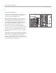
Wine Storage Equipment 3 subzero.com Wine Storage Equipment The importance of the installation of the Sub-Zero wine storage unit cannot be overemphasized. Installation should be done by a qualified installer. RATING PLATE Before you begin the installation process, it is recommended that you read this entire installation guide. There are key details that you should take special care to observe during the installation.
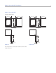
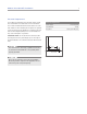
Models 424 and 424FS Installation 4 Models 424 and 424FS OVERALL DIMENSIONS 23 7/8" (606) 24" (610) 24 1/4" (616) 24 5/8" (625) 34" 34 3/16" (864) (868) 4" (102) 4" (102) 25 3/8" 25 3/8" (645) (645) 2 3/8" (60) MODEL 424 Door swing clearances are based on stainless steel door and handle dimensions.
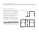
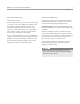
Models 424 and 424FS Installation 5 subzero.com Models 424 and 424FS Installation The model 424FS wine storage unit is designed to be attractive in a stand alone setting. Model 424 must be built in. Refer to the previous page for overall dimensions and door swing clearances for models 424 and 424FS. OPENING DIMENSIONS TOP VIEW 24" (610) OPENING DEPTH Make sure that the finished rough opening where the model 424 wine storage unit is to be installed is properly prepared. Refer to the illustration.
Models 424 and 424FS Installation 6 Electrical Requirements For models 424 and 424FS, the electrical supply should be located within the shaded area shown in the illustration. Follow the National Electrical Code and local codes and ordinances when installing the receptacle. A separate circuit, servicing only this appliance is required. A ground fault circuit interrupter (GFCI) is not recommended and may cause interruption of operation.
Models 424 and 424FS Installation 7 subzero.com Electrical Requirements Unpacking and Moving HOME ALARM SYSTEM Uncrate the unit, remove its wood base and discard the shipping bolts that hold the wood base to the bottom of the unit. Remove all packing materials and tape. If a home alarm system is to be used, refer to home alarm connections on page 11. In addition to operating power, the installer may also be required to supply a home automation system lead to the unit.
Models 424 and 424FS Installation 8 Anti-Tip Bracket Installation MODEL 424FS To prevent the unit from tipping forward and provide a stable installation, the unit must be secured in place with the anti-tip bracket. An anti-tip bracket and hardware is provided with the wine storage unit. The anti-tip bracket must be installed on a solid base to prevent tipover in case several loaded wine shelves are extended at the same time.
Models 424 and 424FS Installation 9 subzero.com Anti-Tip Bracket Installation WOOD FLOOR APPLICATIONS INSTALL CONCRETE WEDGE ANCHORS: Use the four #12 x 21 /2" wood screws and the four 1/4" flat washers provided. Drill pilot holes 3/16" (5) diameter maximum, and be sure that the screws penetrate through the flooring material and into the wall plate a minimum of 3/4" (19). Be sure that the screws hold tight. Refer to the illustration below.
Models 424 and 424FS Installation 10 Lock Installation IMPORTANT NOTE: If you are adding an accessory lock kit to your wine storage unit, it should be installed before you position the unit. The accessory lock kit and additional instructions are available through your authorized Sub-Zero dealer, or call Sub-Zero at 800-222-7820. You can also visit our website at subzero.com.
Models 424 and 424FS Installation 11 subzero.com Level the Unit Home Alarm Connections Using an adjustable wrench or pliers, turn each of the four leveling legs clockwise to raise the unit and counterclockwise to lower the unit. Refer to the illustration below for location of the leveling legs. Before the kickplate is installed, all necessary wiring connections in the compressor compartment should be completed. For model 424, the countertop bracket should be used to make a solid installation.
Models 424 and 424FS Installation 12 Kickplate Installation Door Panel—Model 424 Once the unit is leveled and wiring connections made, the kickplate can be installed. Use the two #10 x 1/2" stainless steel screws that are provided with the kickplate. Refer to the illustration below. Model 424 is offered in two design applications; stainless steel (/S) and overlay (/O). Each of these designs have a full-view glass door. IMPORTANT NOTE: The kickplate must be removed for servicing.
Models 424 and 424FS Installation 13 subzero.com Overlay Door Panel—Model 424 Inspect the door panel for the minimum 5/8" (16) thickness, the finished inside edge. The glass door has a 10 lbs (5 kg) weight limit. Refer to the wine storage section of the Sub-Zero design guide for additional panel information.
Models 424 and 424FS Installation 14 Overlay Door Panel—Model 424 IMPORTANT NOTE: Install screws in all the mounting holes in the door frame. The nature of the door panel with a narrow outer rim and no connecting center member requires the support provided by the glass door. After the door panel installation is complete, apply the cover patches or plugs provided over the holes on the inside surface of the door.
Models 424 and 424FS Installation 15 subzero.com Hinge Adjustment Complete the Installation IMPORTANT NOTE: The wine storage unit must be installed and leveled before door hinge adjustments can be made. IMPORTANT NOTE: When you have completed the installation of the model 424 or 424FS wine storage unit, refer to page 54 for an installation checklist and page 55 for service information.
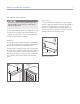
Models 427 and 427R Installation 16 Models 427 and 427R OVERALL DIMENSIONS 27" (686) 24" (610) 27" (686) 14" (356) 24" (610) 14" (356) 13/16" (21) 13/16" (21) 78 9/16" 78 9/16" (1995) (1995) 80" 80" (2032) OPENING HEIGHT (2032) OPENING HEIGHT 3/8" (10) 1/2" (13) 13 1/4" (337) 10 1/4" 34 1/2" (876) (260) 20 3/8" (518) 8 15/16" 9 3/4" (227) (248) 4" HEIGHT DIMENSIONS ± 1/2" (13) 4" HEIGHT DIMENSIONS ± 1/2" (13) (102) 24" 24" (610) (610) (102) 4 5/8" 4 5/8" (117) (117)
Models 427 and 427R Installation 17 subzero.com Models 427 and 427R Installation Refer to the previous page for overall dimensions and door swing clearances for models 427 and 427R. OPENING DIMENSIONS TOP VIEW Make sure that the finished rough opening where the wine storage unit is to be installed is properly prepared. Refer to the illustration for rough opening dimensions for models 427 and 427R. The floor under the unit must be level with the surrounding finished floor.
Models 427 and 427R Installation 18 Electrical Requirements For models 427 and 427R, the electrical supply should be located within the shaded area shown in the illustration. Follow the National Electrical Code and local codes and ordinances when installing the receptacle. A separate circuit, servicing only this appliance is required. A ground fault circuit interrupter (GFCI) is not recommended and may cause interruption of operation.
Models 427 and 427R Installation 19 subzero.com Electrical Requirements Unpacking and Moving HOME ALARM SYSTEM Uncrate the unit, remove its wood base and discard the shipping bolts that hold the wood base to the bottom of the unit. Remove all packing materials and tape. If a home alarm system is to be used, refer to wiring connections on page 24. In addition to operating power, the installer may also be required to supply a home automation system lead to the unit.
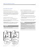
Models 427 and 427R Installation 20 Anti-Tip Bracket Installation An anti-tip bracket and hardware is provided with the wine storage unit. The anti-tip bracket must be installed on a solid base to prevent tipover in case several loaded wine shelves are extended at the same time. If you are installing the model 427 or 427R in a space deeper than 24" (610), the anti-tip bracket must be installed no more than 24" (610) deep, so it engages the unit properly.
Models 427 and 427R Installation 21 subzero.com Anti-Tip Bracket Installation Position Unit INSTALL CONCRETE WEDGE ANCHORS: IMPORTANT NOTE: For model 427R, the top drawer has a control cable that needs to be disconnected before removing this drawer. Refer to the illustration below for placement and how to disconnect this fitting. 1) Drill a 3/8" (10) diameter hole any depth exceeding the minimum embedment. Clean the hole or continue drilling additional depth to accommodate drill fines.
Models 427 and 427R Installation 22 Lock Installation For models 427 and 427R, the optional lock is attached to the decorative door panel through a field-drilled hole in the panel. The catch should be installed on the top of appliance cabinet before the unit is moved into position. The accessory lock kit and additional instructions are available through your authorized Sub-Zero dealer, or call Sub-Zero at 800-222-7820. You can also visit our website at subzero.com.
Models 427 and 427R Installation 23 subzero.com Leveling Install Molding Level the unit by turning the front leveling legs clockwise to raise the unit, or counterclockwise to lower it. To assist you in adjusting the front leveling legs up or down, use a standard screwdriver blade and place it in the front leveling leg as shown in the illustration below. The decorative white molding strips for the top and sides of models 427 and 427R can be snapped into place as shown in the illustrations below.
Models 427 and 427R Installation 24 Wiring Connections Before the kickplate/grille is installed, all necessary wiring connections in the compressor compartment should be completed. If the dual installation heater kit is used with model 427 or 427R, the power supply leads should be connected according to instructions included with the kit. If a home alarm system is to be installed on the wine storage unit, the connections should be made using the logic supplied with the alarm specifications.
Models 427 and 427R Installation 25 subzero.com Kickplate/Grille Door Panels Once the unit is leveled and wiring connections made, the kickplate/grille can be installed. The mounting bracket may be adjusted slightly forward or back so the kickplate/ grille will fit flush with the surrounding area. Refer to the illustration below. Models 427 and 427R have a full-view glass door. Each of these wine storage units are set up at the job site as either the stainless steel or integrated design.
Models 427 and 427R Installation 26 Stainless Steel Door Panel Overlay Door Panel Before installing the stainless steel door panel, check the panel carefully. Options are available for kickplate/grille height, overall height, door swing and door lock. Inspect the door panel for the minimum 5/8" (16) thickness, the greater width requirements for the stiles (to cover the door hinges), and the finished inside edge. The glass door panel has a weight limit of 20 lbs (9 kg).
Models 427 and 427R Installation 27 subzero.com Overlay Door Panel The screw holes inside the door are hidden under a cover flap on the door gasket. It is necessary to lift the flap to insert the screws. Use as many screws as necessary to hold the door panel in place properly. IMPORTANT NOTE: Install screws in all the mounting holes in the door frame. The nature of the door panel with a narrow outer rim and no connecting center member requires the support provided by the glass door.
Models 427 and 427R Installation 28 Model 427R Drawer Panels IMPORTANT NOTE: Drawer panels for model 427R must be a minimum of 5/8" (16) thick and cannot exceed 12 lbs (5 kg) for each panel. Remove the mounting hardware provided and set aside. You should work on the back side of each drawer panel and you should protect the fronts of these panels. Position the top edge of the drawer template flush with the top edge of each drawer.
Models 427 and 427R Installation 29 subzero.com Side Panels 90° Door Stop Side panels for models 427 and 427R are not attached to the unit. You must securely fasten the panels to adjacent cabinets and floor. Models 427 and 427R have a 90° door stop built into the hinge system. Use the blade edge of a standard screwdriver and rotate the brass cam in the center portion of the hinge until you reach the stop. You must make this adjustment to both the bottom and top hinge. Refer to the illustration below.
Model WS-30 Installation 30 Model WS-30 Installation Make sure that the actual equipment that was shipped to you matches the design you are expecting to install. Before you begin the installation process, check the exact model number you need against the model number on the shipping carton. If the unit you receive does not match your requirements, contact your authorized Sub-Zero dealer.
Model WS-30 Installation 31 subzero.com Site Preparation Make sure that the finished rough opening where the wine storage unit is being installed is properly prepared. Refer to installation specifications on the following pages. These specifications are identical for the framed, overlay and stainless steel applications. Installation specifications are different for the flush inset application, whether you are using custom panels or Sub-Zero accessory flush inset panels.
Model WS-30 Installation 32 Standard Installation Opening Dimensions Framed, Overlay and Stainless Steel Models TOP VIEW 24" (610) OPENING DEPTH 24" (610) OPENING DEPTH SIDE VIEW 83 3/4" (2127) OPENING HEIGHT 29 1/2" (746) OPENING WIDTH FRONT VIEW IMPORTANT NOTE: If two units are installed side by side, refer to page 34 for dual standard installations. Stainless steel models are ready to install out of the box.
Model WS-30 Installation 33 subzero.
Model WS-30 Installation 34 Dual Standard Installation Opening Dimensions Framed, Overlay and Stainless Steel Models TOP VIEW 24" (610) OPENING DEPTH 24" (610) OPENING DEPTH 83 3/4" A (2127) OPENING HEIGHT OPENING WIDTH SIDE VIEW FRONT VIEW Opening Widths A Two 30" (762) Models 59 3/4" Model WS-30 and a 36" (914) Model 65 3/4" (1670) (1518) IMPORTANT NOTE: A dual installation kit will be required for this installation. Stainless steel models are ready to install out of the box.
Model WS-30 Installation 35 subzero.
Model WS-30 Installation 36 Electrical Requirements For model WS-30, the electrical supply should be located within the shaded area shown in the illustration. Follow the National Electrical Code and local codes and ordinances when installing the receptacle. A separate circuit, servicing only this appliance is required. A ground fault circuit interrupter (GFCI) is not recommended and may cause interruption of operation.
Model WS-30 Installation 37 subzero.com Unpack the Unit Grille Removal Uncrate the unit and inspect for any damages. Remove the wood base and discard the shipping bolts and brackets that hold the wood base to the bottom of the unit. Remove and discard all packing materials. In order to prevent damage to the grille and to access the power cord, the top grille assembly should be removed prior to moving the unit. IMPORTANT NOTE: Do not discard the kickplate, anti-tip brackets and hardware.
Model WS-30 Installation 38 Anti-Tip Bracket Installation To prevent the unit from tipping forward and provide a stable installation, the unit must be secured in place with the anti-tip brackets shipped with the unit. IMPORTANT NOTE: For either wood or concrete floor applications, if the #12 x 2 1/2" screws do not hit a wall stud or the wall plate in any of the back holes of the brackets, use the provided #8–18 x 1 1/4" PH truss HD screws and #12 flat washers with the nylon zip-it wall anchors.
Model WS-30 Installation 39 subzero.com Anti-Tip Bracket Installation CONCRETE FLOOR APPLICATIONS INSTALL CONCRETE WEDGE ANCHORS: After properly locating the anti-tip brackets in the rough opening, drill pilot holes 3/16" (5) diameter maximum in the wall studs and/or wall plate. Then drill 3/8" (10) diameter holes into the concrete a minimum of 11/2" (38) deep.
Model WS-30 Installation 40 Position the Unit Level the Unit Use an appliance dolly to move the unit near the rough opening. Model WS-30 is equipped with rollers, so it can be moved into position more easily. Once the unit is in position, extend the front leveling legs down by turning the legs clockwise to adjust the height. The rear height adjustment can be made from the front of the base. Use a 3/8" socket to adjust the rear rollers.
Model WS-30 Installation 41 subzero.com Door Adjustment The door of the model WS-30 can be adjusted in three ways: In and out, side to side tilt, and up and down. Regardless of the adjustment being made, start by slightly loosening the two upper hinge bolts on the upper hinge plate using a 1/2" wrench. Refer to the illustration below. DOOR HEIGHT ADJUSTMENT To adjust a left-hinge door; using a 1/4" allen wrench, turn the bolt clockwise to raise the door and counterclockwise to lower the door.
Model WS-30 Installation 42 Anchoring Home Alarm Connections After door and side panels have been installed, the unit has been leveled and door adjustment completed, anchor the wine storage unit to the opening. This will assure a proper fit and a secure installation. If a home alarm system is to be installed on the wine storage unit, the connections should be made using the logic supplied with the alarm specifications.
Model WS-30 Installation 43 subzero.com Complete the Installation—Model WS-30/S Panel Installation For framed, overlay and flush inset applications, refer to the following pages for front and side panel information. Before you install the front panel, refer to panel specifications for framed, overlay or flush inset applications and be sure you are working with the panel design called for in your installation.
Model WS-30 Installation 44 Framed Panel If your customer has chosen a framed design application, make sure that the panel you are about to install matches dimensions listed in the framed panel specifications on the following page. Additional panel design information can be found in the Sub-Zero design guide and on our website, subzero.com. If the thickness of the custom panel is less than a 1/4" (6), back it up with a sheet of shim material to build the total thickness to a 1/4" (6).
Model WS-30 Installation 45 subzero.com Framed Panel Framed Panel Specifications RAISED PANEL With some door panel designs, you may have to rout, recess or use optional extended handles to allow for finger clearance. This is particularly true if your unit has raised panels greater than 1/4" (6) total thickness. Check the location of offset when you’re using specific routing for the grip area only. Refer to the Sub-Zero design guide for a full-scale template of the standard full-length handle and panel.
Model WS-30 Installation 46 Overlay Panels If your customer has chosen an overlay design application, make sure that the panels you are about to install match dimensions listed in the overlay panel specifications on the following page. Additional panel design information can be found in the Sub-Zero wine storage design guide and on our website, subzero.com. IMPORTANT NOTE: The size of the overlay panel is critical. It must fit over the door frame.
Model WS-30 Installation 47 subzero.com Overlay Panels Overlay Panel Specifications GRILLE PANEL ASSEMBLY Remove the grille panel assembly as described on page 37. Remove the top two corner screws and pull away the top frame. Slide the panel into position in the grille frame. If you are using a grille panel 1/4" (6) or thinner, you will need to install a filler. Reattach the top frame by reinstalling the two top corner screws.
Model WS-30 Installation 48 Flush Inset Panels If your customer has chosen the flush inset panel application, make sure that the panels you are about to install match dimensions listed in the flush inset panel specifications on the following page. Additional panel design information can be found in the Sub-Zero design guide and on our website, subzero.com. IMPORTANT NOTE: The size of the flush inset panel is critical. It must fit over the door frame.
Model WS-30 Installation 49 subzero.com Flush Inset Panels Remove the grille panel assembly as described on page 37. Remove the top two corner screws and pull away the top frame. Slide the panel into position in the grille frame. If you are using a grille panel 1/4" (6) or thinner, you will need to install a filler. Flush Inset Panel Specifications H A A A H Reattach the top frame by reinstalling the two top corner screws.
Model WS-30 Installation 50 Flush Inset Panel Dual Installations Illustrations A–D provide panel offsets and reveals for model WS-30 in a flush inset application. Refer to the chart below for reference to the illustrations. When two models WS-30 or a model WS-30 and built-in unit are installed side by side, a dual installation kit may be required. Contact your authorized Sub-Zero dealer for the proper components and installation instructions.
Model WS-30 Installation 51 subzero.com Dual Installations Flush Inset Panels—Dual Installation DUAL FLUSH INSET INSTALLATIONS H Installing two models WS-30 or a model WS-30 and built-in unit side by side in a flush inset application will require adjustments to the dimensions of your finished rough opening, panel sizes and panel offsets. It will also require a dual installation kit, available through your authorized Sub-Zero dealer.
Model WS-30 Installation 52 Flush Inset Panels—Dual Installation When installing two models WS-30 or a model WS-30 and built-in unit side by side in a flush inset application, you must decrease the width of the decorative flush inset panels by 1/2". Adjustments to the panel offsets will also need to be made. These adjustments are needed to achieve a proper fit and to ensure the panels do not collide when closing.
Model WS-30 Installation 53 subzero.com Side Panels IMPORTANT NOTE: Side panels will need to be installed before the unit is placed in its final position. When installing a model WS-30 with a custom side panel, an accessory kit is required. Stainless steel and white enamel side panels are available through your authorized Sub-Zero dealer. Refer to instructions included with the side panel kit when installing these side panels.
Installation Checklist 54 Complete the Installation For framed, overlay and flush inset applications, follow these steps to complete the installation. Before installing the kickplate, be sure to reinstall the drain pan. Once the drain pan is in place, screw the kickplate the to brackets attached to the inside surface of each roller base. Reinstall the grille following the instructions on page 37. Turn power back on to the electrical outlet.
Service Information 55 subzero.com Service Information If service is necessary, maintain the quality built into your Sub-Zero unit by calling a Sub-Zero authorized service center. To obtain the name and number of a Sub-Zero authorized service center, check the contact & support section of our website, subzero.com or call Sub-Zero customer service at 800-222-7820. If you are storing or disposing of your old refrigerator or freezer, please do it safely. Remove the doors or tightly secure the doors closed.
SUB-ZERO, INC. P. O. BOX 44848 MADISON, WI 53744 7011714 REV-A 7/ 2010 SUBZERO.COM 800.222.