INSTALLATION GUIDE PRO 48 Refrigeration
Contents Important Note PRO 48 Refrigeration . . . . . . . . . . . . . . . . . . . . . . . . . . . . 3 To ensure the safe and efficient installation of Sub-Zero equipment, please take note of the following types of highlighted information throughout this guide: PRO 48 Specifications . . . . . . . . . . . . . . . . . . . . . . . . . . . 4 PRO 48 Site Preparation . . . . . . . . . . . . . . . . . . . . . . . . . . 5 PRO 48 Installation . . . . . . . . . . . . . . . . . . . . . . . . . . . . . .
PRO 48 Refrigeration 3 subzero.com/specs Sub-Zero PRO 48 Refrigeration Before You Start The importance of the installation of the Sub-Zero PRO 48 unit cannot be overemphasized. Installation should be done by a qualified installer. Make sure the opening dimensions, door and drawer clearances, electrical service and plumbing are correct for the model you are about to install. Refer to specifications on the following pages.
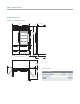
PRO 48 Specifications 4 Overall Dimensions MODELS 648PRO AND 648PROG 25 7/8" (657) 48" (1219) 84" (2134) 42 1/8" (1070) 30 1/2" (775) 4" (102) HEIGHT DIMENSIONS ± 1/2" (13) 30 3/16" (767) 23 7/8" (606) 14 1/2" 21" (533) (368) SPECIFICATIONS 30 3/4" (781) Capacity / Weight INTERIOR CAPACITY 648PRO and 648PROG SHIPPING WEIGHT 2 3/8" (60) 648PRO 648PROG R CU FT (L) F CU FT (L) 18.4 (521) 11.
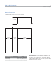
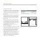
PRO 48 Site Preparation 5 subzero.com/specs Opening Dimensions STANDARD AND FLUSH BUILT-IN INSTALLATIONS TOP VIEW OPENING DEPTH OPENING DEPTH OPENING WIDTH OPENING HEIGHT SIDE VIEW Opening Dimensions FRONT VIEW Standard Flush Opening Width 47 1/2" (1206) 48" (1219) Opening Height 83 3/4" Opening Depth (2127) 84 1/8" (2137) 24" (610) 26" (660) IMPORTANT NOTE: For standard built-in installations, the face frame of the unit will extend 2" (51) beyond cabinetry.
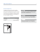
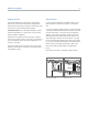
PRO 48 Site Preparation 6 Electrical Requirements For PRO 48 models, the electrical supply should be located within the shaded area shown in the illustration below. Follow the National Electrical Code and local codes and ordinances when installing the receptacle. A separate circuit, servicing only this appliance is required. A ground fault circuit interrupter (GFCI) is not recommended and may cause interruption of operation. Do not use an extension cord or two-prong adapter.
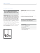
PRO 48 Site Preparation 7 subzero.com/specs Plumbing Requirements The PRO 48 has an automatic ice maker with an integrated water filtration system. The water supply line should be located within the shaded area shown in the illustrations. The water line must not interfere with installation of the anti-tip bracket. Plumbing Requirements 1/4" Water Supply Line Water Pressure 35–120 psi (2.4–8.
PRO 48 Installation 8 Anti-Tip Bracket Installation To prevent the PRO 48 from tipping forward and provide a stable installation, the unit must be secured in place with the anti-tip bracket provided with the unit. IMPORTANT NOTE: Placement of the anti-tip bracket is critical to a stable installation. Failure to properly position the anti-tip bracket will prevent it from engaging the unit.
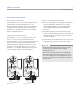
PRO 48 Installation 9 subzero.com/specs Anti-Tip Bracket Installation WOOD FLOOR APPLICATIONS INSTALL CONCRETE WEDGE ANCHORS: Use the twelve #12 x 2 1/2" wood screws and the twelve #12 flat washers provided. Drill pilot holes 3/16" (5) diameter maximum and make sure the screws penetrate through the flooring material and into the wall plate a minimum of 3/4" (19). Make sure the screws hold tight. Refer to the illustration below.
PRO 48 Installation 10 Unpack the Unit Grille Removal Uncrate the PRO 48 unit and inspect for any damages. Remove the wood base and discard the shipping bolts and brackets that hold the wood base to the bottom of the unit. Remove and discard all packing materials. In order to prevent damage to the PRO 48 grille, the top grille assembly should be removed prior to moving the unit. IMPORTANT NOTE: Do not discard the kickplate, anti-tip bracket and hardware or corner protectors.
PRO 48 Installation 11 subzero.com/specs Position the Unit Before moving the PRO 48 unit into position, secure doors and drawers closed and protect any finished flooring. Use an appliance dolly to move the unit near the rough opening. The PRO 48 is equipped with rollers, so it can be moved into position more easily. When securing the unit on the appliance dolly, use the corner protectors (retained from the packing materials) under the strapping to avoid damage to the stainless steel exterior.
PRO 48 Installation 12 Water Line Connection Level the Unit Approximately 3' (.9 m) of 1/4" plastic tubing is connected to the ice maker with a preassembled 1/4" compression connection at the end. This tubing is located under the unit. Once the unit is in position, extend the front leveling legs down by turning the legs counterclockwise and adjust the height. The rear height adjustment can be made from the front of the base. Use a 5/16" socket to adjust the rear rollers.
PRO 48 Installation 13 subzero.com/specs Door Adjustment Make sure both doors of the PRO 48 are properly aligned for function and appearance. If not, adjustments can be made to the cabinet hinges. The doors of the PRO 48 are very heavy. Use care when removing them. IMPORTANT NOTE: The unit must be properly leveled before adjusting hinges. If the PRO 48 is properly installed and leveled, it may still be necessary to adjust doors left to right.
PRO 48 Installation 14 Drawer Adjustment Make sure all drawers of the PRO 48 are properly aligned for function and appearance. If not, vertical and horizontal adjustments can be made to the drawers. The drawer must be removed to make vertical and horizontal adjustments. To remove the drawer, pull the drawer all the way out until it stops, lift up evenly on both sides of the drawer front and pull out. To reinstall the drawer, raise the front of the drawer and place onto the drawer slide tracks.
PRO 48 Installation 15 subzero.com/specs Complete the Installation Optional Accessories INSTALL KICKPLATE 90° DOOR STOP Make sure the drain pan is in the proper position before installing the kickplate. To install, screw the kickplate to brackets attached to the inside surface of each roller base. Refer to the illustration below. The doors of PRO 48 models open to 135°.
PRO 48 Installation 16 Water Filtration System WATER FILTER BYPASS MODE If you choose not to use the water filtration system, the system can be placed in water filter bypass mode by removing the water filter cartridge. In this mode, the water supplied to the ice maker will not be filtered and the water filter monitor will be deactivated. WATER FILTER Lift the top grille assembly to access the water filter cartridge.
PRO 48 Installation 17 subzero.com/specs Installation Checklist To ensure a safe and proper installation, the following checklist should be completed by the installer to ensure that no part of the installation has been overlooked. INSTALLATION CHECKLIST Have all packing materials been removed? Turn the unit on.
Service Information 18 Service Information If service is necessary, maintain the quality built into your PRO 48 unit by calling Sub-Zero factory certified service. For the name and number of Sub-Zero factory certified service nearest you, check the contact & support section of our website, subzero.com or call Sub-Zero customer service at 800-222-7820. When calling for service, you will need the model and serial number of your unit.
The information and images in this guide are the copyright property of Sub-Zero, Inc. Neither this guide nor any information or images contained herein may be copied or used in whole or in part without the express written permission of Sub-Zero, Inc. ©Sub-Zero, Inc. all rights reserved. Wolf, Wolf & Design, Wolf Gourmet, W & Design and the color red as applied to knobs are registered trademarks and service marks of Wolf Appliance, Inc.
SUB-ZERO, INC. P. O. BOX 44848 MADISON, WI 53744 7020379 REV-A 10 / 2010 SUBZERO.COM 800.222.