CEILING-MOUNTED HOOD INSTALLATION GUIDE S P E C I F I C AT I O N S , I N S TA L L AT I O N , A N D M O R E
C E ILING -MO UNTE D HOOD Contents 3 Ceiling-Mounted 4 Site Important Note Hood Preparation 6 Specifications To ensure this product is installed and operated as safely and efficiently as possible, take note of the following types of highlighted information throughout this guide: IMPORTANT NOTE highlights information that is especially 8 Hood Installation: Internal Blower important.
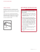
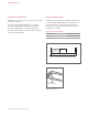
C E ILING -MO UNTE D HOOD Product Information Important product information, including the model and serial number, are listed on the product rating plate. The rating plate is located under the left side of the hood, above the filters (filters must be removed). Refer to the illustration below. If service is necessary, contact Wolf Factory Certified Service with the model and serial number.
S I T E PR EPAR ATION Ducting WARNING Use only metal ducting. IMPORTANT NOTE: Consult a qualified HVAC professional for specific installation and ducting applications. The hood accommodates a 6" (152) round duct. Use only rigid metal ducting. A straight, short duct run is most effective and will ensure proper performance. If the duct run exceeds 50' (15 m), a higher CFM blower may be required to maintain proper airflow. A remote blower installed on a short duct run may increase the potential for noise.
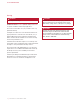
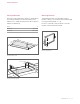
S I T E PR EPAR ATION Ducting Filter Removal R ECIR CULAT ING APPL ICATION To access the grease filters, pull down the front edge of the bottom panel of the hood and allow it to rotate downward. The hood with an internal blower, can be installed in a recirculating application. The air discharge must be a minimum of 40" (1016) from every side of the hood. Refer to the illustration below. To remove the filters, refer to the illustration below.
S PECIF ICAT IO NS Installation Requirements Electrical Requirements Install the hood 36" (914) to 84" (2134) from the bottom of the hood to the countertop. Installation must comply with all applicable electrical codes. The hood requires a 600 CFM internal or in-line blower assembly, or a 600 CFM or 1200 CFM remote blower assembly, available through an authorized Wolf dealer. Consult a qualified HVAC professional for specific installation and ducting applications.
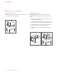
S PECIF ICAT IO NS Ceiling Preparation Mounting Brackets Refer to the chart and illustrations below for opening dimensions and typical framing. Construct the framing using minimum 2" x 4" lumber. Framing must be able to support a minimum of 100 lb (45 kg). To determine the height of the adjustable mounting brackets, subtract 5" (127) from the support framing height (e.g. support framing height – 5" = H).
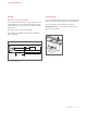
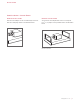
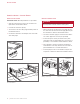
I N S TALLAT IO N Hood Installation—Internal Blower B LO WER B O X RE MOVAL B LO W ER I N S TALLATI O N Remove the blower box from the hood by removing the four screws. Refer to the illustration below. IMPORTANT NOTE: The blower must be installed and plugged in prior to making the electrical connection to the hood. 1 Insert the round discharge on the blower into the round discharge on the blower box. 2 Secure the blower to the blower box with the two screws provided with the blower.
I N S TALLAT IO N Hood Installation—Internal Blower D A MPER INS TAL L ATION B R AC K ET I N S TA LLATI O N Place the round damper on the round discharge and secure with duct sealing tape. Refer to the illustration below. Secure the two mounting brackets to the hood using the four 9/16" (14) length screws provided. Refer to the illustration below. Damper installation Bracket installation wolfappliance.
I N S TALLAT IO N Hood Installation—Internal Blower H OO D INS TALLATION IMPORTANT NOTE: Mounting hardware is not provided. 1 Verify the control panel on the hood is located on the right. Refer to the illustration below. 2 Insert W I R I N G C O N N EC TI O N S WARNING Before making electrical connections, make sure the electrical power is turned off at the service panel. the hood into the opening. 3 Secure the hood to the ceiling support framing. Refer to the illustration below.
I N S TALLAT IO N Hood Installation—In-Line/Remote Blower B LO WER B O X RE MOVAL FLAN GE I N S TALLATI O N 1 Remove 1 Place the blower box from the hood by removing the four screws. Refer to the illustration below. 2 Discard the blower box and screws. Blower box removal the flange on the top of the hood. the flange to the hood with the 1/4" (6) length screws provided. Refer to the illustration below. 2 Secure Flange installation wolfappliance.
I N S TALLAT IO N Hood Installation—In-Line/Remote Blower B R ACKET INS TA L L ATION H O O D I N S TALLATI O N Secure the two mounting brackets to the hood using the four 9/16" (14) length screws provided. Refer to the illustration below. IMPORTANT NOTE: Mounting hardware is not provided. 1 Verify the control panel on the hood is located on the right. Refer to the illustration below. 2 Insert the hood into the opening. 3 Secure the hood to the ceiling support framing.
I N S TALLAT IO N Hood Installation—In-Line/Remote Blower W IR ING CO NNECTIONS WARNING Before making electrical connections, make sure the electrical power is turned off at the service panel. Home Supply: 1 Remove the knockout above the home supply junction box, then insert the home electrical supply (Romex) into the electrical box. Refer to the illustration below. 2 Secure the electrical supply to the electrical box with a UL or C/UL approved connector (not provided).
T R O UB LES HO O TING Completion Troubleshooting 1 Install IMPORTANT NOTE: If the hood does not operate properly, follow these troubleshooting steps: the grease filters. Refer to the illustration below. 2 Rotate the bottom cover upward and into position. 3 Turn on the electrical supply at the circuit panel and verify operation. 1 Verify electrical power is supplied to the hood. 2 Verify proper wiring connections. 3 If FILTER Filter installation 14 | Wolf Customer Care 800.
Sub-Zero, Sub-Zero & Design, Sub-Zero & Snowflake Design, Dual Refrigeration, The Living Kitchen, Great American Kitchens The Fine Art of Kitchen Design, Wolf, Wolf & Design, Wolf Gourmet, W & Design, red colored knobs, Cove, and Cove & Design are registered trademarks and service marks of Sub-Zero Group, Inc. and its subsidiaries. All other trademarks are property of their respective owners in the United States and other countries. wolfappliance.
C A MPANA INS TAL ADA E N E L TE CHO Contenido 3 Campana Aviso importante instalada en el techo 4 Preparación del sitio 6 Especificaciones Para garantizar que este producto se instale y opere de la forma más segura y eficiente posible, tome nota de los siguientes tipos de información resaltada en este manual: AVISO IMPORTANTE señala la información que es especial- 8 Instalación de la campana: Extractor interno mente importante.
C A MPANA INS TAL ADA E N E L TE CHO Información del producto La información importante del producto, incluido el modelo y número de serie de la unidad, se encuentra en la placa de datos del producto, que está debajo del costado izquierdo de la campana, encima de los filtros (se deben retirar los filtros). Consulte la siguiente ilustración. Si es necesario realizar algún servicio, póngase en contacto con el Servicio certificado de fábrica de Wolf y tenga a mano el modelo y el número de serie.
P REPAR ACIÓ N DE L SITIO Conductos ADVERTENCIA Utilice solamente conductos metálicos. Consulte a un profesional de climatización calificado para la instalación específica y las aplicaciones de conductos. La campana admite un conducto redondo de 6" (152). Utilice solamente conductos metálicos rígidos. Los tramos de conductos cortos y rectos son más efectivos y garantizarán un desempeño adecuado.
P REPAR ACIÓ N DE L SITIO Conductos Extracción del filtro A P LICACIÓ N DE RE CIRCUL ACIÓN Para acceder a los filtros de grasa, hale hacia abajo el borde frontal del panel inferior de la campana y déjelo rotar hacia abajo. La campana con un extractor interno se puede instalar en una aplicación de recirculación. La descarga de aire debe ser de un mínimo de 40" (1016) desde cada lado de la campana. Consulte la siguiente ilustración. No se suministran los conductos y la tapa de la ventilación.
ES PECIF ICACIONE S Requisitos de instalación Instalación eléctrica Instale la campana a 36" (914) y 84" (2134) de distancia desde La instalación debe cumplir con todos los códigos eléctricos vigentes. la parte inferior de la campana a la encimera. La campana requiere que se instale un extractor 600 CFM interno o en línea o 600 CFM o 1200 CFM remoto, que se puede obtener a través de un distribuidor autorizado de Wolf.
ES PECIF ICACIONE S Preparación del techo Soportes para montaje Consulte en la tabla y las ilustraciones siguientes las dimensiones de abertura y la estructura típica. Construya la estructura con madera de 2" x 4" como mínimo. La estructura debe poder soportar un peso mínimo de 100 lb (45 kg). Para determinar la altura de los soportes de montaje ajustables, reste 5" (127) de la altura de la estructura de soporte (por ejemplo, altura de la estructura de soporte – 5" = Altura).
I N S TALACIÓ N Instalación de la campana - Extractor interno EX T R ACCIÓ N DE L A CAJA DE L E XTRACTOR I N S TALA C I Ó N D EL EX TR A C TO R Retire la caja del extractor de la campana quitando los cuatro tornillos. Consulte la siguiente ilustración. AVISO IMPORTANTE: el extractor se debe instalar y enchufar antes de realizar la conexión eléctrica a la campana. 1 Inserte la descarga redonda del extractor en la descarga redonda en la caja del extractor.
I N S TALACIÓ N Instalación de la campana - Extractor interno I N S TALACIÓ N D E L A COMPUE RTA I N S TALA C I Ó N D E LO S S O P O RTES Coloque la compuerta redonda en la descarga redonda y asegure con cinta para sellado de conductos. Consulte la siguiente ilustración. Asegure los dos soportes de montaje a la campana con los cuatro tornillos de 9/16" (14) de largo proporcionados. Consulte la siguiente ilustración. Instalación de la compuerta Instalación de los soportes wolfappliance.
I N S TALACIÓ N Instalación de la campana - Extractor interno I N S TALACIÓ N D E L A CAMPANA AVISO IMPORTANTE: no se suministran herrajes para montaje. 1 Verifique que el panel de control en la campana esté ubicado a la derecha. Consulte la siguiente ilustración. 2 Inserte C O N EX I O N ES D E C A B LEAD O ADVERTENCIA Antes de realizar las conexiones eléctricas, asegúrese de que la corriente eléctrica esté apagada en el panel de servicio. la campana en la abertura.
I N S TALACIÓ N Instalación de la campana - Extractor en línea/remoto EX T R ACCIÓ N DE L A CAJA DE L E XTRACTOR 1 Retire la caja del extractor de la campana quitando los cuatro tornillos. Consulte la siguiente ilustración. 2 Deseche I N S TA LAC I Ó N D E LA B R I D A 1 Coloque la brida en la parte superior de la campana. la brida a la campana con los tornillos de 1/4" (6) de largo provistos. Consulte la siguiente ilustración. 2 Asegure la caja del extractor y los tornillos.
I N S TALACIÓ N Instalación de la campana - Extractor en línea/remoto I N S TALACIÓ N D E L OS SOPORTE S Asegure los dos soportes de montaje a la campana con los cuatro tornillos de 9/16" (14) de largo proporcionados. Consulte la siguiente ilustración. I N S TA LAC I Ó N D E LA C A MPAN A AVISO IMPORTANTE: no se suministran herrajes para montaje. 1 Verifique que el panel de control en la campana esté ubicado a la derecha. Consulte la siguiente ilustración. 2 Inserte la campana en la abertura.
I N S TALACIÓ N Instalación de la campana - Extractor en línea/remoto C ONEX IO NES DE CABL E ADO ADVERTENCIA Antes de realizar las conexiones eléctricas, asegúrese de que la corriente eléctrica esté apagada en el panel de servicio. Suministro en línea/remoto: 1 Retire el prepunzonado sobre la caja de derivación del extractor en línea/remoto, luego introduzca el suministro eléctrico del extractor (Romex) en la caja eléctrica.
R ES O LUCIÓ N DE PROBL E MAS Finalización Solución de problemas 1 Instale AVISO IMPORTANTE: si la campana no funciona correctamente, siga estos pasos para resolver problemas: 2 Rote 1 Compruebe que la campana tiene corriente eléctrica. 2 Compruebe que las conexiones de cableado estén los filtros de grasa. Consulte la siguiente ilustración. la tapa inferior hacia arriba y hacia su posición. 3 Encienda el suministro eléctrico en el panel de circuitos y verifique el funcionamiento.
Sub-Zero, Sub-Zero & Design, Sub-Zero & Snowflake Design, Dual Refrigeration, The Living Kitchen, Great American Kitchens The Fine Art of Kitchen Design, Wolf, Wolf & Design, Wolf Gourmet, W & Design, red colored knobs, Cove, and Cove & Design son marcas registradas y marcas de servicio de Sub-Zero Group, Inc. y sus filiales. Todas las demás marcas registradas son propiedad de sus dueños respectivos en los Estados Unidos y otros países. wolfappliance.
H OT T E INS TALLÉ E AU PL AFOND Table des matières Remarque importante 3 Hotte 6 Spécifications Pour s’assurer que ce produit est installé et utilisé en toute sécurité et aussi efficacement que possible, prenez note des types de renseignement mis en évidence tout au long de ce guide : 8 Installation de la hotte: ventilateur interne REMARQUE IMPORTANTE met en évidence des renseigne- 11 Installation de la hotte: ventilateur en ligne/à distance ments qui sont particulièrement importants.
H OT T E INS TALLÉ E AU PL AFOND Renseignements sur le produit Des renseignements importants sur le produit, y compris les numéros de modèle et de série, se trouvent sur la plaque signalétique du produit. La plaque signalétique est située sous le côté gauche de la hotte, au-dessus des filtres (les filtres doivent être enlevés). Reportez-vous à l’illustration ci-dessous. Si vous avez besoin de service, communiquez avec le service Wolf certifié par l’usine avec les numéros de modèle et de série.
P RÉPAR AT IO N D U SITE Gaines AVERTISSEMENT Utilisez uniquement des gaines métalliques. Consultez un professionnel en CVC qualifié pour des installations et des applications de gaines précises. La hotte accepte une gaine ronde de 6 po (152). Utilisez uniquement des gaines métalliques rigides. Un tracé de gaines court et droit est plus efficace et assure une meilleure performance.
P RÉPAR AT IO N D U SITE Gaines Retrait du filtre A P PLICAT IO N D E RE MISE E N CIRCUL ATION Pour accéder aux filtres à graisse, tirez le rebord avant du panneau inférieur de la hotte vers le bas et laissez-le pivoter vers le bas. La hotte avec un ventilateur interne peut être installée dans une application de remise en circulation. L’évacuation d’air doit mesurer au moins 40 po (1016) de chaque côté de la hotte. Reportez-vous à l’illustration ci-dessous.
S PÉCIF ICAT IO NS Exigences d’installation Électricité Installez la hotte à une distance de 36 po (914) à 84 po (2 134) de la partie inférieure de la hotte jusqu’au comptoir. L’installation doit se conformer à tous les codes électriques applicables. La hotte nécessite un assemblage de ventilateur 600 CFM interne ou a en ligne ou à 600 CFM ou a 1200 CFM distance, offert par les dépositaires Wolf autorisés. Repérez l’alimentation électrique dans la zone ombragée indiquée dans l’illustration ci-dessous.
S PÉCIF ICAT IO NS Préparation du plafond Supports de montage Reportez-vous au tableau et aux illustrations ci-dessous pour la dimension des ouvertures et du cadre typique. Effectuez le cadre en utilisant du bois mesurant au moins 2 x 4 po (51 x 102). Le cadre doit pouvoir soutenir une charge d’au moins 100 lb (45 kg). Pour déterminer la hauteur des supports de montage réglables, soustrayez 5 po (127) de la hauteur du cadre de soutien (p. ex., hauteur du cadre de soutien – 5 po = H).
I N S TALLAT IO N Installation de la hotte—ventilateur interne R ET R AIT DU B OÎTIE R DU VE NTIL ATE UR I N S TALLATI O N D U VEN TI LATEU R Retirez le boîtier du ventilateur de la hotte en retirant les quatre vis. Reportez-vous à l’illustration ci-dessous. REMARQUE IMPORTANTE : Le ventilateur doit être installé et branché avant d’effectuer la connexion électrique jusqu’à la hotte. 1 Insérez l’évacuation ronde située sur le ventilateur dans l’évacuation ronde située sur le boîtier du ventilateur.
I N S TALLAT IO N Installation de la hotte—ventilateur interne I N S TALLAT IO N D U RE GISTRE I N S TALLATI O N D ES S U P P O RTS Placez le registre rond sur l’évacuation ronde et fixez avec du ruban adhésif en toile. Reportez-vous à l’illustration ci-dessous. Fixez les deux supports de montage à la hotte en utilisant les quatre vis de 9/16 po (14) de longueur fournies. Reportez-vous à l’illustration ci-dessous. Installation du registre Installation des supports wolfappliance.
I N S TALLAT IO N Installation de la hotte—ventilateur interne I N S TALLAT IO N D E L A HOTTE REMARQUE IMPORTANTE : La quincaillerie de montage n’est pas fournie. 1 Vérifiez que le panneau de commande de la hotte se trouve du côté droit. Reportez-vous à l’illustration ci-dessous. 2 Insérez la hotte dans l’ouverture. 3 Fixez la hotte au cadre de soutien au plafond. Reportez-vous à l’illustration ci-dessous. 4 Reliez les gaines au registre, puis fixez avec du ruban adhésif en toile.
I N S TALLAT IO N Installation de la hotte—ventilateur en ligne/à distance R ET R AIT DU B OÎTIE R DU VE NTIL ATE UR 1 Retirez le boîtier du ventilateur de la hotte en retirant les quatre vis. Reportez-vous à l’illustration ci-dessous. 2 Éliminez I N S TA LLATI O N D E LA B R I D E 1 Placez la bride sur le dessus de la hotte. la bride à la hotte avec les vis de 1/4 po (6) de longueur fournies. Reportez-vous à l’illustration ci-dessous. 2 Fixez le boîtier du ventilateur et les vis.
I N S TALLAT IO N Installation de la hotte—ventilateur en ligne/à distance I N S TALLAT IO N D E S SUPPORTS Fixez les deux supports de montage à la hotte en utilisant les quatre vis de 9/16 po (14) de longueur fournies. Reportez-vous à l’illustration ci-dessous. I N S TA LLATI O N D E LA H O TTE REMARQUE IMPORTANTE : La quincaillerie de montage n’est pas fournie. 1 Vérifiez que le panneau de commande de la hotte se trouve du côté droit. Reportez-vous à l’illustration ci-dessous.
I N S TALLAT IO N Installation de la hotte—ventilateur en ligne/à distance C ONNEX IO NS AVERTISSEMENT Avant d’effectuer des connexions électriques, assurez-vous que l’alimentation est coupée au niveau du panneau de service. Alimentation résidentielle : 1 Retirez l’alvéole défonçable située au-dessus de la boîte de connexion résidentielle, puis insérez le fil d’alimentation résidentiel (Romex) dans le coffret électrique. Reportez-vous à l’illustration ci-dessous.
D É PANNAG E Achèvement Dépannage 1 Installez REMARQUE IMPORTANTE : Si la hotte ne fonctionne pas les filtres à graisse. Reportez-vous à l’illustration ci-dessous. 2 Basculez le couvercle inférieur vers le haut pour le replacer. 3 Rétablissez l’alimentation électrique au niveau du panneau de circuit et vérifiez le fonctionnement. FILTRE Installation du filtre 14 | Service à la clientèle de Wolf 800.222.
Sub-Zero, Sub-Zero & Design, Sub-Zero & Snowflake Design, Dual Refrigeration, The Living Kitchen, Great American Kitchens The Fine Art of Kitchen Design, Wolf, Wolf & Design, Wolf Gourmet, W & Design, les boutons de couleur rouge, Cove et Cove & Design sont des marques déposées et de service de Sub-Zero Group, Inc. et ses filiales. Toutes les autres marques de commerce appartiennent à leurs propriétaires respectifs aux États-Unis et dans d’autres pays. wolfappliance.
WOLF APPLI ANCE , I NC. P. O. BOX 44848 MA D I SO N , WI 5 3 7 4 4 828138 REV-C 10 / 2018 WO L FA P P L I A N C E. C O M 8 0 0 . 2 2 2.