21.04.
Sehr geehrter Kunde! Sehr geehrte Kundin! Wir möchten Ihnen herzlich danken, dass Sie sich zum Erwerb eines Produkts aus unserem reichhaltigen Angebot entschieden haben. Lesen Sie die gesamte Bedienungsanleitung, bevor Sie das Gerät zum ersten Mal benutzen. Verwahren Sie diese Bedienungsanleitung zur zukünftigen Verwendung an einem sicheren Ort. Falls Sie das Gerät weitergeben, müssen Sie diese Bedienungsanleitung ebenfalls mit übergeben. Inhalt 1. Sicherheitshinweise .....................................
10. Garantiebedingungen ................................................................................................ 40 A. Technische Zeichnung / Technical drawing............................................................ 76 Entsorgen Sie dieses Gerät nicht zusammen mit ihrem Hausmüll. Das Gerät darf nur über eine Sammelstelle für wiederverwendbare elektrische und elektronische Geräte entsorgt werden. Entfernen Sie nicht die Symbole / Aufkleber am Gerät.
1. Sicherheitshinweise LESEN SIE VOR DER ERSTEN BENUTZUNG DES GERÄTES DIE GESAMTEN SICHERHEITSHINWEISE UND SICHERHEITSANWEISUNGEN GRÜNDLICH DURCH. Die darin enthaltenen Informationen dienen dem Schutz Ihrer Gesundheit. Die Nichtbeachtung der Sicherheitshinweise kann zu schweren Beeinträchtigungen Ihrer Gesundheit und im schlimmsten Fall zum Tod führen. Bewahren Sie diese Bedienungsanleitung so auf, dass sie bei Bedarf jederzeit griffbereit ist.
1.1 Signalwörter GEFAHR! verweist auf eine Gefahrensituation, die, wenn sie nicht abgewendet wird, eine unmittelbare Gefährdung für Leben und Gesundheit zur Folge hat. WARNUNG! verweist auf eine Gefahrensituation, die, wenn sie nicht abgewendet wird, eine mögliche bevorstehende Gefährdung für Leben und Gesundheit zur Folge hat. VORSICHT! verweist auf eine Gefahrensituation, die, wenn sie nicht abgewendet wird, zu mittelschweren oder kleineren Verletzungen führen kann.
Dunstabzugshaube im Umluftbetrieb benutzen, ist der gleichzeitige Betrieb einer raumluftabhängigen Feuerstätte unbedenklich. 6. Falls es in Ihrer Wohnung zum Austritt eines brennbaren Gases kommen sollte: a) Öffnen Sie alle Fenster zur Belüftung. b) Ziehen Sie nicht den Stecker aus der Steckdose und benutzen Sie nicht das Bedienfeld bzw. die Schalter. c) Berühren Sie nicht das Gerät, bis sämtliches Gas abgezogen ist. d) Bei Missachtung dieser Anweisungen können Funken entstehen, die das Gas entflammen. 7.
6. Ihr Hausstrom muss mit einem Sicherungsautomaten zur Notabschaltung des Gerätes ausgestattet sein. 7. Vor Installation des Gerätes muss die Arbeitsplatte der Küchenzeile auf Tragfähigkeit und Belastbarkeit geprüft werden! Das Gesamtgewicht der Dunstabzugshaube beträgt ca. 20,50 Kilo. Die Installation des Gerätes darf nur an geeigneter Stelle erfolgen. 8. Bereiten Sie niemals flambierte Gerichte zu. Die offenen Flammen können das Gerät zerstören und einen Brand verursachen. 9.
1. Zugängliche und berührbare Teile der Haube können heiß werden, wenn die Haube zusammen mit einer Kochvorrichtung benutzt wird. 2. Führen Sie den Einbau des Gerätes mit mindestens zwei Personen durch, weil Sie ansonsten das Gerät beschädigen oder der Person, die an dem Gerät arbeitet, Schaden zufügen. HINWEIS! 1. Das Gerät muss von mindestens zwei Personen transportiert und angeschlossen werden. 2. Entfernen Sie sämtliches Verpackungsmaterial, bevor Sie das Gerät benutzen.
die durch unsachgemäße Installation des Gerätes entstehen, unterliegen weder der Garantie noch der Gewährleistung! Die Dunstabzugshaube wird zwischen Kochfeld und Wand in die Arbeitsplatte der Küchenzeile eingebaut und ist zum Einsatz als Umlufthaube vorgerüstet. Achten Sie darauf, dass für den Einbau der Dunstabzugshaube ausreichend freier Installationsraum (Arbeitsplatte / Einbauschrank: unterhalb des Kochfelds) vorhanden ist; siehe auch Kapitel A. TECHNISCHE ZEICHNUNG.
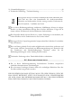
2 BELEUCHTUNG 3 FETTFILTER 4 5 AUSFAHRBARER DUNSTABZUG ➢ S. Kapitel 4. BEDIENFELD UND BEDIENUNG ff. GEHÄUSE (befindet sich nach dem Einbau unterhalb der Arbeitsplatte / s. Abb. unten) Abb. ähnlich: Modifikationen sind möglich. 4 AUSFAHRBARER DUNSTABZUG 5 GEHÄUSE 6 ARBEITSPLATTE 7 MOTORGEHÄUSE 8 ABLUFTAUSLASS / RÜCKSCHLAGKLAPPE 2.
WARNUNG! Eine Nichtbeachtung der Installationsanweisungen für die Schrauben oder Befestigungsvorrichtungen kann zu einem Stromschlag führen! HINWEIS! Sie benötigen mindestens zwei Personen zur Installation des Gerätes. BENÖTIGTE WERKZEUGE3 (NICHT IM LIEFERUMFANG ENTHALTEN) BLEISTIFT MAßBAND HAMMER SCHRAUBENDREHER WASSERWAAGE BOHRMASCHINE UND / ODER AKKUSCHRAUBER INSTALLATIONSSCHRITTE 1.
A ARBEITSPLATTE / INSTALLATIONSÖFFNUNG 2. Entfernen Sie die beiden Metallstützen (C) mit Hilfe eines Schraubendrehers vom Gehäuse der Dunstabzugshaube (B); s. Abb. unten. Verwahren Sie die Metallstützen (C) und die Schrauben (D / 4 St. M4*12) an einem sicheren Ort; sie werden im Laufe der Installation wieder benötigt. 3. Entfernen Sie außerdem die Abdeckung der elektronischen Kontrollbox / Kabellagerung (E) mit Hilfe eines Schraubendrehers vom Gehäuse der Dunstabzugshaube (B); s. Abb. unten.
B DUNSTABZUGSHAUBE: GEHÄUSE C METALLSTÜTZEN / 2 ST. D SCHRAUBEN DER METALLSTÜTZEN / 4 ST. M4*12 E ABDECKUNG DER ELEKTRONISCHEN KONTROLLBOX / KABELLAGERUNG F SCHRAUBEN DER ABDECKUNG / 6 ST. ST3*12 4. Setzen Sie die Dunstabzugshaube vorsichtig in die Installationsöffnung ein; s. Abb. unten. A ARBEITSPLATTE / INSTALLATIONSÖFFNUNG B DUNSTABZUGSHAUBE: GEHÄUSE B1 DUNSTABZUGSHAUBE: AUFLAGEFLÄCHE DES GEHÄUSES 5.
A ARBEITSPLATTE / INSTALLATIONSÖFFNUNG B DUNSTABZUGSHAUBE B1 DUNSTABZUGSHAUBE: AUFLAGEFLÄCHE DES GEHÄUSES; siehe auch Abb. unten. B DUNSTABZUGSHAUBE: GEHÄUSE B1 DUNSTABZUGSHAUBE: AUFLAGEFLÄCHE DES GEHÄUSES B2 DUNSTABZUGSHAUBE: EIN- UND AUSFAHRBAR 6. Befestigen Sie die Metallstützen (C) mit den entsprechenden Schrauben (D / 4 St. M4*12) auf dem Gehäuse der Dunstabzugshaube; s. Abb. unten. Justieren Sie die Metallstützen entsprechend dem Abstand zum Boden bzw.
A ARBEITSPLATTE B DUNSTABZUGSHAUBE: GEHÄUSE C METALLSTÜTZEN / 2 ST. C1 JUSTIERBEREICH DER METALLSTÜTZEN D SCHRAUBEN DER METALLSTÜTZEN / 4 ST. M4*12 7. Entfernen Sie die 4 Schrauben (G), die das Motorgehäuse auf dem Gehäuse der Dunstabzugshaube (B) befestigen; s. Abb. unten. Verwahren Sie die Schrauben gut.
B DUNSTABZUGSHAUBE: GEHÄUSE G SCHRAUBEN: MOTORGEHÄUSE 8. Verbinden Sie die entsprechenden Kabel (Dunstabzugshaube: Gehäuse ↔ Motorgehäuse) ordnungsgemäß. Die Klemmen der Kabel haben alle eine unterschiedliche Form, so dass es keine Möglichkeit gibt, diese falsch anzuschließen. Die Pfeile zeigen die unterschiedlichen Klemmen der Kabel; s. Abb. unten. 9. Installieren Sie das Motorgehäuse (H) ordnungsgemäß mit den entsprechenden Schrauben (s. Schritt 7) auf dem Gehäuse der Dunstabzugshaube (B): s. Abb.
A ARBEITSPLATTE B DUNSTABZUGSHAUBE: GEHÄUSE C METALLSTÜTZEN E ABDECKUNG DER ELEKTRONISCHEN KONTROLLBOX / KABELLAGERUNG H MOTORGEHÄUSE 11. Befestigen Sie die Metallstütze4 (C 2) mit den entsprechenden Schrauben auf dem Motorgehäuse; s. Abb. unten. Justieren Sie die Metallstütze entsprechend dem Abstand zum Boden bzw. dem Abstand zum Boden des Einbauschranks. Die Metallstütze muss fest auf dem Boden stehen. Der feste Kontakt der Metallstütze mit dem Boden bzw.
A ARBEITSPLATTE B DUNSTABZUGSHAUBE: GEHÄUSE C METALLSTÜTZEN C1 JUSTIERBEREICH DER METALLSTÜTZEN C2 METALLSTÜTZE: MOTORGEHÄUSE H MOTORGEHÄUSE 12. Wenn sich die Dunstabzugshaube in ihrer endgültigen Position befindet, verschrauben Sie die Metallstützen mit dem Boden, um eine möglichst große Stabilität zu erreichen. 13. Setzen Sie die Fettfilter ein (s. Abb. in Kapitel 2.1 GERÄTEANSICHT) und schließen Sie das Netzkabel ordnungsgemäß am Stromnetz an.
WICHTIGE INSTALLATIONSHINWEISE FÜR DEN OPTIONALEN ABLUFTBETRIEB WARNUNG! Die Installation für den Abluftbetrieb muss durch qualifiziertes Fachpersonal ausgeführt werden! WARNUNG! Die Abluft darf nicht in einen Schornstein geleitet werden, der für Abgase von Geräten, die mit Gas oder anderen Brennstoffen betrieben werden, genutzt wird. ❖ Sie können das Gerät auch im Abluftbetrieb verwenden (optional). ❖ Im Abluftbetrieb wird die angesaugte Luft durch einen Abluftschlauch nach außen geführt.
10. Je nach Modell kann Ihre Abzugshaube mit einer (oben) oder zwei (oben und hinten) Abzugsöffnungen ausgestattet sein. Die nicht benötigte Öffnung ist mit einem Kunststoffdeckel versehen, der durch Drehen gegen den Uhrzeigersinn entfernt und auf die nicht benötigte Öffnung gesetzt werden kann. 2.3 Elektrischer Anschluss Prüfen Sie vor dem Anschluss der Dunstabzugshaube an das Stromnetz, ob die auf dem Typenschild angegeben Spannung mit der Netzspannung Ihrer Wohnung übereinstimmt.
Ersetzen Sie die KOHLEFILTER regelmäßig; siehe auch Kapitel REINIGUNG UND PFLEGE. KOHLEFILTER für Ihre Dunstabzugshaube sind als optionales Zubehör erhältlich. Bestellen Sie KOHLEFILTER unter www.pkm-online.de ➢ Typbezeichnung der KOHLEFILTERS: Siehe Kapitel TECHNISCHE DATEN WARNUNG! Schalten Sie das Gerät vor der Montage von Kohlefiltern unbedingt aus und trennen Sie es von der Stromversorgung (entsprechende Sicherung im Haussicherungskasten). INSTALLATION DES KOHLEFILTERS 1.
Abb. ähnlich: Modifikationen sind möglich. 1 KOHLEFILTER 2 FLACHER TEIL DES KUNSTSTOFFRAHMEN DES KOHLEFILTERS 3 SPALT ZUR AUFNAHME DES KOHLEFILTERS 4 GEHÄUSE DER DUNSTABZUGSHAUBE 5 MOTORGEHÄUSE 2. Wenn Sie den Kohlefilter austauschen möchten (siehe auch Kapitel 6.2 AUSTAUSCH DES KOHLEFILTERS), ziehen Sie ihn vorsichtig aus dem Spalt heraus und ersetzen Sie ihn durch einen neuen Filter. WARNUNG! Achten Sie darauf, dass der Kohlefilter ordnungsgemäß eingesetzt ist.
HINWEIS! Wechseln Sie den Kohlefilter je nach Benutzung der Haube mindestens alle drei bis sechs Monate. Reinigen Sie für einen einwandfreien Betrieb des Motors den Fettfilter regelmäßig (s. Kapitel REINIGUNG UND PFLEGE). 3.2 Fettfilter Achten Sie darauf, dass die Fettfilter immer ordnungsgemäß eingesetzt sind. Reinigen Sie die Fettfilter regelmäßig; s. Kapitel REINIGUNG UND PFLEGE.
« EIN / AUS » - TASTE und DIGITALANZEIGE ➢ Taste zum Ein- und Ausschalten (Aus- und Einfahren) der Dunstabzugshaube. ➢ Gleichzeitig ist diese Taste eine Digitalanzeige und zeigt den aktuellen Status der Dunstabzugshaube an (Leistungsstufe, Countdown - Zeit). « ERHÖHEN » - TASTE ➢ Taste zur Erhöhung der Leistungsstufe (Motorgeschwindigkeit). BELEUCHTUNG: « EIN / AUS » 4.
4. Sie können jederzeit mit den Tasten « VERRINGERN » und / oder « ERHÖHEN » die Leistungsstufe nach Bedarf anpassen. 5. Wenn Sie die Dunstabzugshaube einfahren bzw. ausstellen möchten, gehen Sie bitte wie folgt vor: a. Stellen Sie die Leistungsstufe mit der « VERRINGERN » - TASTE auf « 0 ». Falls die Beleuchtung eingeschaltet ist, schalten Sie diese mit der TASTE « BELEUCHTUNG » aus. b. Das Gerät befindet sich jetzt im STANDBY - MODUS. Die Digitalanzeige zeigt « 0 »; der Motor ist ausgeschaltet. c.
2. Stellen Sie mit der « VERRINGERN » - TASTE und / oder der « ERHÖHEN » - TASTE die gewünschte Leistungsstufe / Motorgeschwindigkeit (1 - 9) ein; siehe auch Kapitel 4.2.1 LEISTUNGSSTUFEN. 3. Berühren und halten Sie die « TIMER » - TASTE für 3 Sekunden, um die Einstellung der Countdown - Zeit zu aktivieren. Die Digitalanzeige blinkt. 4. Stellen Sie die gewünschte Countdown - Zeit mit den Tasten « VERRINGERN » und / oder « ERHÖHEN » ein (1 Minute - 9 Minuten). 5.
❖ Mit der « VERRINGERN » - TASTE können Sie die Leistungsstufe (Motorgeschwindigkeit) der Dunstabzugshaube verringern; siehe auch Kapitel 4.2.1 LEISTUNGSSTUFEN. ❖ Sie können mit dieser Taste außerdem die Countdown - Zeit des Timers verringern. « ERHÖHEN » - TASTE ❖ Mit der « ERHÖHEN » - TASTE können Sie die Leistungsstufe (Motorgeschwindigkeit) der Dunstabzugshaube erhöhen; siehe auch Kapitel 4.2.1 LEISTUNGSSTUFEN. ❖ Sie können mit dieser Taste außerdem die Countdown - Zeit des Timers erhöhen.
Verringern Sie die Leistungsstufe (Motorgeschwindigkeit) mit der « VERRINGERN » - TASTE auf « 0 », wechselt das Gerät in den STANDBY - MODUS. Sie müssen immer zuerst die Leistungsstufe (Motorgeschwindigkeit) mit der « VERRINGERN » - TASTE auf « 0 » stellen (STANDBY - MODUS), um die Dunstabzugshaube mit der « EIN / AUS » - TASTE einfahren und damit ausschalten zu können.
➢ Nutzen Sie die Leistungsstufen (Motorgeschwindigkeiten) « 7 - 9 », falls Ihr Kochgut viel Dampf generiert (hohe Konzentration von Kochdünsten) oder falls Sie eine besonders starke Leistung benötigen (z. B. bei überaus starker Dampfentwicklung und sehr starker Konzentration von Kochdünsten). 5. Umweltschutz 5.1 Umweltschutz: Entsorgung ❖ Geräte mit diesem Zeichen « » dürfen innerhalb der gesamten EU nicht zusammen mit dem Hausmüll entsorgt werden.
❖ Da saubere Filter die Effizienz des Gerätes steigern, reinigen Sie regelmäßig den / die Fettfilter. ❖ Tauschen Sie die Kohlefilter (Verwendung nur im Umluftbetrieb) regelmäßig aus. Achten Sie hierbei auf die Hinweise des Herstellers der Kohlefilter. 6. Reinigung und Pflege WARNUNG! Trennen Sie das Gerät vor allen Wartungs- und Reinigungsarbeiten von der Stromversorgung.
FOLGENDE PRODUKTE DÜRFEN FÜR DIE REINIGUNG NICHT VERWENDET WERDEN ➢ ➢ ➢ ➢ ➢ ➢ ➢ ➢ ➢ ➢ ➢ Produkte, die Chloride enthalten; insbesondere solche, die Salzsäure enthalten. Produkte auf Halogenidbasis. Produkte auf der Basis von Wasserstoffperoxid. Hypochlorsäurebleiche. Aggressive Produkte, die Säuren enthalten. Reinigungsmittel, die Scheuerpulver enthalten. Reinigungsprodukte für Silber. Reinigungsmittel, deren chemische Zusammensetzung unbekannt ist. Scheuerpads, Bürsten oder Scheiben.
Aluminium - Fettfilter brauchen nicht ersetzt werden. Sie müssen allerdings regelmäßig gereinigt werden. ❖ Reinigen Sie die Fettfilter regelmäßig von Hand oder in der Spülmaschine (bis 65 °C). ❖ Verwenden Sie keine aggressiven Reinigungsmittel. ❖ Benutzen Sie keine Scheuermittel! ❖ Benutzen Sie keine alkalischen Spülmaschinenreiniger (pH größer 7). REINIGUNGSINTERVALL FÜR ALUMINIUM - FETTFILTER ➢ Alle 2 - 3 Wochen Dunstabzugshaube.
6.2 Austausch des Kohlefilters WARNUNG! Schalten Sie das Gerät vor der Montage von Kohlefiltern unbedingt aus und trennen Sie es von der Stromversorgung (entsprechende Sicherung im Haussicherungskasten). KOHLEFILTER für Ihre Dunstabzugshaube sind als optionales Zubehör erhältlich. ❖ Herkömmliche Kohlefilter können nicht gereinigt werden. ❖ Diese Filter haben eine begrenzte Aufnahmefähigkeit und sind in der Regel nach ca. 3 Monaten verbraucht. ❖ Ersetzen Sie einen verbrauchten Filter umgehend.
WARNUNG! Das LED - Leuchtmittel darf nur durch eine fachkundige Person ausgewechselt werden. Führen Sie den Austausch des LED Leuchtmittels niemals eigenständig aus. Falls das LED - Leuchtmittel beschädigt ist, wenden Sie sich an eine qualifizierte Fachkraft (Elektrotechniker/-in) / (keine Garantieleistung!). HINWEISE FÜR DIE QUALIFIZIERTE FACHKRAFT (ELEKTROTECHNIKER/-IN) WARNUNG! Trennen Sie das Gerät von der Stromversorgung (entsprechende Sicherung im Haussicherungskasten).
6. Drücken Sie das LED - Leuchtmittel vorsichtig in seine Halterung, bis es hörbar einrastet. Erforderlicher Minimalabstand zu Oberflächen wie Topfdeckeln, Topflappen etc. zur Vermeidung heißwerdender Teile und Brandrisiken. --- m = 0,45 m Zur Vermeidung unangemessen heißwerdender Teile, Brandrisiken und einer Strahlenbelastung durch UV-Strahlung dürfen ausschließlich selbstabschirmende Leuchtmittel verwendet werden.
1. Das Gerät ist mit dem Netzstecker 1. Schließen Sie das Gerät nicht an der Steckdose ordnungsgemäß an die Steckdose an. angeschlossen. 2. Der Netzstecker ist locker. 2. Überprüfen Sie den Netzstecker. 3. Die Steckdose wird nicht mit Strom 3. Überprüfen Sie die fragliche versorgt. Steckdose, indem Sie ein anderes Gerät daran anschließen. 4. Die entsprechende Sicherung ist 4. Überprüfen Sie die Haussicherung. ausgeschaltet. 5. Die Spannung ist zu niedrig 5.
WENN DIE LEISTUNG DER HAUBE UNZUREICHEND IST UND / ODER ERHÖHTE BETRIEBSGERÄUSCHE ZU HÖREN SIND, KÖNNEN DAFÜR DIE FOLGENDEN URSACHEN VORLIEGEN. IM UMLUFTBETRIEB ➢ Überprüfen Sie den Zustand und die Sauberkeit der Filter. ➢ Falls Sie die Haube im Umluftbetrieb verwenden, überprüfen Sie, ob die Kohlefilter rechtzeitig gewechselt wurden (mindestens alle 3 - 6 Monate). IM ABLUFTBETRIEB (OPTIONAL) ➢ Unzureichende Größe der Abluftleitung. ➢ Eine Verstopfung in der Abluftleitung.
TECHNISCHE DATEN* Geräteart Material Einbaubreite in cm Umluftbetrieb / Abluftbetrieb** Jährlicher Energieverbrauch (AEChood) Energieeffizienzklasse*** Fluiddynamische Effizienz (FDEhood) Fluiddynamische Effizienzklasse Beleuchtungseffizienz (LEhood) Beleuchtungseffizienzklasse Fettabscheidegrad Fettabscheidegradklasse Luftstrom **** Maximaler Luftstrom Qmax Luftstrom im Betrieb auf der Intensivstufe oder Schnellaufstufe A-bewertete Luftschallemission **** A-bewertete Luftschallemission im Betrieb auf der I
** Nur Abluftbetrieb: bei Anschluss an einen Entlüftungskamin bzw. Abluft ins Freie (Mauerdurchführung = Ø N/A, Bohrung Ø N/A: Falls nötig, kontaktieren Sie bitte den Kundendienst). *** Auf einer Skala von A+++ (beste) bis D (schlechteste). **** Messwerte bei minimaler /maximaler Motorgeschwindigkeit. ***** Ausstattung abhängig vom Modell. 9. Entsorgung 1.
10. Garantiebedingungen Der Hersteller leistet dem Verbraucher für die Dauer von 24 Monaten, gerechnet vom Tag des Kaufes Garantie für einwandfreies Material und fehlerfreie Fertigung. Dem Verbraucher stehen neben den Rechten aus der Garantie die gesetzlichen Gewährleistungsrechte zu, die der Verbraucher gegen den Verkäufer hat, bei dem er das Gerät erworben hat. Diese werden durch die Garantie nicht eingeschränkt.
Dear customer! We would like to thank you for purchasing a product from our wide range of domestic appliances. Read the complete instruction manual before you operate the appliance for the first time. Retain this instruction manual in a safe place for future reference. If you transfer the appliance to a third party, also hand over this instruction manual. Index 1. Safety instructions........................................................................................................ 43 1.
A. Technische Zeichnung / Technical drawing............................................................ 76 Do not dispose of this appliance together with your domestic waste. The appliance must be disposed of at a collecting centre for recyclable electric and electronic appliances. Do not remove the symbol from the appliance. The figures in this instruction manual may differ in some details from the current design of your appliance. Nevertheless, follow the instructions in such a case.
1. Safety instructions READ THE SAFETY INFORMATION AND THE SAFETY INSTRUCTIONS CAREFULLY BEFORE YOU OPERATE THE APPLIANCE FOR THE FIRST TIME. All information included in those pages serve for the protection of the operator. If you ignore the safety instructions, you will endanger your health and life. Store this manual in a safe place so you can use it whenever it is needed. Strictly observe the instructions to avoid damage to persons and property.
1.1 Signal words DANGER! indicates a hazardous WARNING! indicates a hazardous situation which, if ignored, will result in situation which, if ignored, could result death or serious injury. in death or serious injury. CAUTION! indicates a hazardous NOTICE! indicates possible damage to situation which, if not avoided, may the appliance. result in minor or moderate injury. 1.2 Safety instructions DANGER! To reduce the risk of electrocution. 1.
7. Never pull the power supply cable to unplug the appliance. Always use the power plug itself to unplug the appliance. RISK OF ELECTRIC SHOCK! 8. Never touch the power plug, the power switch or other electrical components with wet or damp hands. RISK OF ELECTRIC SHOCK! WARNING! To reduce the risk of burns, electrocution, fire or injury to persons. 1.
13. Disconnect the appliance from the mains before cleaning and maintenance. 14. Failure to follow the cleaning instructions will increase the RISK OF FIRE due to fat deposits. 15. While unpacking, the packaging materials (polythene bags, polystyrene pieces, etc.) should be kept away from children. CHOKING HAZARD! 16. Always supervise children when they are near the appliance. 17. Children must not play with the appliance. 18.
2. Installation WARNING! The load-bearing capacity of the worktop in the kitchen must be checked before you install the appliance. The total weight of the extractor hood is approx. 20.50 kilos. The appliance must be installed at a suitable position only. NOTICE! The installation of the extractor hood should be carried out by qualified professionals.
2.1 View of the appliance Fig. similar: modifications are possible. 1 CONTROL PANEL // « ON / OFF » - SENSOR ➢ S. chapter 4. CONTROL PANEL AND OPERATION et seq. 2 ILLUMINATION 3 GREASE FILTERS 4 5 EXTENDABLE EXTRACTOR HOOD ➢ S. chapter 4. CONTROL PANEL AND OPERATION et seq. HOUSING (is below the worktop after installation / s. fig.
Fig. similar: modifications are possible. 4 EXTENDABLE EXTRACTOR HOOD 5 HOUSING OF THE EXTRACTOR HOOD 6 WORKTOP 7 MOTOR HOUSING 8 EXHAUST AIR OUTLET / ONE-WAY VALVE 2.2 Installation steps WARNING! Failure to install the screws or fixing the appliance in accordance with these instructions may result in electrical hazards. NOTICE! The appliance must be installed by at least two persons. REQUIRED TOOLS14 (NOT INCLUDED IN DELIVERY) PENCIL 14 MEASURING TAPE Depending on model.
REQUIRED TOOLS15 (NOT INCLUDED IN DELIVERY) HAMMER BUBBLE LEVEL SCREWDRIVER DRILL AND / OR CORDLESS SCREWDRIVER INSTALLATION STEPS 1. Measure the worktop and prepare the installation opening for the extractor hood according to the dimensions in the following figure (see below). Ensure that there is sufficient free installation space for the installation of the extractor hood.
3. Also remove the cover of the electronic control box / cable storage (E) from the housing of the extractor hood (B) using a screwdriver (s. fig. below). Keep the cover (E) and the screws (F / 6 pcs. ST3*12) in a safe place; they will be needed again during the installation. A WORKTOP / INSTALLATION OPENING B EXTRACTOR HOOD: HOUSING C METAL SUPPORTS / 2 pcs. D SCREWS OF THE METAL SUPPORTS / 4 pcs. M4*12 E COVER OF THE ELECTRONIC CONTROL BOX / CABLE STORAGE F SCREWS OF THE COVER / 6 pcs.
A WORKTOP / INSTALLATION OPENING B EXTRACTOR HOOD: HOUSING B1 EXTRACTOR HOOD: SUPPORT SURFACE OF THE HOUSING 5. The support surface of the housing (B 1) should lie firmly and flat on the worktop (A / see fig. below). A WORKTOP / INSTALLATION OPENING B EXTRACTOR HOOD B1 EXTRACTOR HOOD: SUPPORT SURFACE OF THE HOUSING (see also fig.
B EXTRACTOR HOOD: HOUSING B1 EXTRACTOR HOOD: SUPPORT SURFACE OF THE HOUSING B2 EXTRACTOR HOOD: RETRACTABLE AND EXTENDABLE 6. Fix the metal supports (C) on the housing of the extractor hood using the appropriate screws (D / 4 pcs. M4*12): see fig. below. Adjust the metal supports according to the distance to the floor or to the distance to the bottom of the builtin cabinet. The metal supports must stand firmly on the ground. Adjust the metal supports accordingly.
A WORKTOP B EXTRACTOR HOOD: HOUSING C METAL SUPPORTS / 2 pcs. C1 ADJUSTMENT RANGE OF THE METAL SUPPORTS D SCREWS OF THE METAL SUPPORTS / 4 pcs. M4*12 7. Remove the 4 screws (G) that fix the motor housing on the housing of the extractor hood (B / see fig. below). Store the screws in a safe place. B EXTRACTOR HOOD: HOUSING G SCREWS: MOTOR HOUSING 8. Connect the corresponding cables (extractor hood: housing ↔ motor housing) properly.
9. Install the motor housing (H) properly on the housing of the extractor hood (B) using the appropriate screws (see step 7): see fig. below. 10. Reinstall the cover of the electronic control box / cable storage (E) properly on the housing of the extractor hood (B) using the appropriate screws (6 pcs. ST3*12): see fig. below. Make sure that the cables are not kinked.
11. Fix the metal support16 (C 2) on the motor housing (s. fig. below). Adjust the metal support according to the distance to the floor or to the distance to the bottom of the built-in cabinet. The metal support must stand firmly on the floor. Adjust the metal support accordingly. The firm contact of the metal support with the floor or the bottom of the built-in cabinet also ensures that the appliance does not vibrate. A WORKTOP B EXTRACTOR HOOD: HOUSING C METAL SUPPORTS / 2 pcs.
IMPORTANT INSTALLATION INSTRUCTIONS: EXTRACTION MODE (OPTIONAL) WARNING! The installation for the operation in extraction mode must be carried out by qualified professionals! WARNING! Do not lead the exhaust air into a chimney which is used for extracting exhaust air of appliances operated by gas or other combustibles. ❖ You can also use the appliance in extraction mode. ❖ In extraction mode, the intake air is led through an exhaust hose to the outside.
2.3 Electrical connection Check that the voltage indicated on the rating plate matches the mains voltage of your home before connecting the extractor hood to the mains. Check that the extractor hood is installed properly before you connect the appliance to the mains. 3. Recirculation mode ❖ The extractor hood is usually ready for the use in recirculation mode. ❖ In recirculation mode, the exhaust air is led back into the kitchen.
WARNING! Switch off the appliance and disconnect it from the mains before you install any carbon filters (use the relevant fuse in your household fuse box). HOW TO INSTALL THE CARBON FILTER 1. The carbon filter (1) is inserted into the gap (3) between the housing of the extractor hood (4) and the motor housing (5): s. fig. below. Ensure that the flat part of the plastic frame (2) of the carbon filter (1) points towards the housing of the extractor hood (4): s. fig. below. Fig.
2 FLAT PART OF THE PLASTIC FRAME OF THE CARBON FILTER 3 GAP TO INSERT THE CARBON FILTER 4 HOUSING OF THE EXTRACTOR HOOD 5 MOTOR HOUSING 2. If you want to replace the carbon filter (see also chapter 6.2 REPLACING OF THE CARBON FILTER), pull it out of the gap carefully and replace it by a new one. WARNING! Always ensure that the carbon filter is inserted properly. NOTICE! The suction capacity is decreased by an installed carbon filter.
« TIMER » - SENSOR ➢ Sensor to set a countdown time (1 minute - 9 minutes) for the automatic switch-off of the extractor hood. « DECREASE » - SENSOR ➢ Sensor to decrease the power level (motor speed). « ON / OFF » - SENSOR and DIGITAL DISPLAY ➢ Sensor to switch on / off (extend / retract) the extractor hood. ➢ This sensor is also a digital display and indicates the current status of the extractor hood (power level, countdown time). « INCREASE » - SENSOR ➢ Sensor to increase the power level (motor speed).
3. Touch the « INCREASE » - SENSOR repeatedly to set the desired power level of the extractor hood (power level 1 - 9). 4. The set power level can be changed at any time using the sensors « DECREASE » and / or « INCREASE ». 5. If you want to retract (= switch off) the extractor hood, proceed as follows. a. Set the power level (motor speed) to « 0 » using the « DECREASE »SENSOR. If the illumination is on, switch it off using the « ILLUMINATION » - SENSOR. b. The appliance is now in STANDBY MODE.
2. Touch the « INCREASE » - SENSOR repeatedly to set the desired power level of the extractor hood (power level 1 - 9). 3. Touch and hold the « TIMER » - SENSOR for 3 seconds to activate the setting of the timer. The digital display flashes. 4. Set the desired countdown time (1 minute to 9 minutes) using the SENSORS « INCREASE » and / or « DECREASE ». 5. When you have set the desired countdown time, touch the « TIMER » - SENSOR again (briefly) to confirm the setting.
❖ You can also use this sensor to increase the countdown time of the timer. ILLUMINANT: « ON / OFF » ❖ You can use the sensor « ILLUMINANT of the appliance. » to switch on or off the ILLUMINANT WARNING! The illuminant must not be covered by thermal insulation or other materials. RISK OF FIRE! CAUTION! Do not touch the illuminant within 30 minutes after using the appliance. RISK OF BURNS! NOTICE! Only switch on the illuminant while the appliance is operating.
❖ When you set the power level (motor speed) to « 0 » using the « DECREASE » - SENSOR, the motor of the extractor hood goes off and the appliance returns to STANDBY MODE. 1-9 HOW TO SET THE POWER LEVELS « 1 - 9 » ❖ To set the desired power level (motor speed), touch the sensors « INCREASE » and / or « DECREASE » repeatedly until the desired power level « 1 - 9 » is indicated on the digital display.
5.1 Environmental protection: disposal ❖ Appliances bearing this symbol « » must not be disposed of together with household waste throughout the EU. To prevent potential damage to the environment or human health from uncontrolled waste disposal and to promote the sustainable reuse of material resources, responsibly supply the appliance to a recycling centre. 5.2 Environmental protection: energy saving ❖ Cover your cookware (cooking pot / pan) with lids during cooking.
NOTICE! Take off all rings and bracelets before cleaning or maintaining the appliance; otherwise, you will damage the surface of the appliance. ❖ The extractor hood must be cleaned regularly: at least once a month! 1. Clean the housing of the appliance with a suitable detergent. Use such a product carefully and economically. 2. Do not clean the control panel with a detergent. Use a damp cloth. Otherwise, you may damage the electronic components of the controls. 3.
❖ To clean stainless-steel surfaces, use a non-abrasive stainless-steel cleaning agent only. NOTICE! Never use stainless steel cleaner for the direct environment of the control panel or the control panel itself. NOTICE! Aggressive detergents such as abrasive detergents, vinegar cleaners, etc. damage the surface of the extractor hood. 6.1 Cleaning of the grease filters WARNING! Failure to follow the cleaning instructions will increase the RISK OF FIRE due to fat deposits.
3. Then clean the grease filters with a soft brush. Be careful not to damage the grid of the grease filters. 4. After cleaning: rinse the grease filters thoroughly using hot water. 5. Repeat this process in case of stubborn soilings or deposits. 6. Dry the grease filters properly before you reinstall them.
REPLACEMENT INTERVAL FOR CARBON FILTERS ➢ At least every 3 - 6 months according to the frequency of use of the extractor hood. You can order the CARBON FILTERS at www.pkm-online.de ➢ Type name of the CARBON FILTERS: See chapter TECHNICAL DATA 6.3 Replacing of the illuminant WARNING! The LED - illuminant must be replaced by a competent person only. Do not carry out the replacement of the LED - illuminant yourself.
3. Pull the LED - illuminant out of its holder carefully. Unplug the illuminant cable (s. fig. below). 4. Replace the used LED - illuminant by a new one of the same type and power. 5. Connect the plug of the illuminant cable with the new LED - illuminant (s. fig. below). 6. Push the new LED - illuminant into its holder carefully until it snaps into place properly. Required minimum distance to surfaces such as pot lids, oven cloths etc. to avoid any hot parts and risk of fire. --- m = 0.
THE APPLIANCE DOES NOT WORK AT ALL. 1. The plug of the appliance is not connected to the socket. 2. The plug has become loose. 3. The socket is not supplied with energy. 4. The fuse is switched off. 5. The voltage is too low. 1. Connect the appliance to the mains properly. 2. Check the plug. 3. Check the corresponding socket by connecting it with another appliance. 4. Check the fuse box. 5. Compare the data on the model plate with the data of your energy supplier. LIGHT IS ON BUT MOTOR DOES NOT WORK. 1.
If the appliance has a malfunction not noted on the schedule or if you have checked all items on the schedule but the problem still exists, please contact the aftersales service. IF THE HOOD DOES NOT WORK PROPERLY AND / OR YOU CAN HEAR INCREASED OPERATING NOISE, CHECK THE SCHEDULE BELOW. IN RECIRCULATION MODE ➢ Check condition and cleanliness of the filters. ➢ When you run your appliance in recirculation mode, check if the carbon filter has been replaced on time (min. every 3-6 months).
Material Installation-width in cm Recirculation / extraction mode** Annual energy consumption (AEChood) Energy efficiency category*** Fluid dynamical efficiency (FDEhood) Fluid dynamical efficiency category Lighting efficiency (LEhood) Lighting efficiency category Grease separation Grease separation category Air flow **** Maximum air flow Qmax Air flow during operation at intensive A-rated noise emission **** A-rated noise emission during operation at intensive or rapid operation setting Power consumption l
9. Waste management 1. While unpacking, the packaging materials (polythene bags, polystyrene pieces, etc.) should be kept away from children and pets. CHOKING HAZARD! 2. Old and unused appliances must be sent for disposal to the responsible recycling centre. Never expose to open flames. 3. Before you dispose of an old appliance, render it inoperative. Unplug the appliance and cut off the entire power cord. Dispose of the power cord and the plug immediately. 4.
The guarantee claim does not cover: 1. fragile components as plastic, glass or bulbs; 2. minor modifications of the WOLKENSTEIN-products concerning their authorised condition if they do not influence the utility value of the product; 3. damage caused by handling errors or false operation; 4. damage caused by aggressive environmental conditions, chemicals, detergents; 5. damage caused by non-professional installation and haulage; 6. damage caused by non common household use; 7.
Alle Abmessungen sind in Millimetern angegeben. All dimensions are given in millimetres.
SERVICE INFORMATION Sie finden alle Informationen zum Kundendienst auf der Einlage in dieser Bedienungsanleitung. Aftersales service information on the leaflet inside this instruction manual. Änderungen vorbehalten Subject to alterations STAND UPDATED 22.04.2021 04/22/2021 © PKM GmbH & Co.