ORION RADIO MODEM WITH I/O OPERATING INSTRUCTIONS 1892 1335 Figure 1 - Orion Radio Modem Figure 2 - Orion Radio Modem - OEM PCB version 1892 1335 - Orion Radio Modem Operating Instructions - v2.
1892 1335 - Orion Radio Modem Operating Instructions - v2.
Contents Contents . . . . . . . . . . . . . . . . . . . . . . . . . . . . . . . . . . . . . . . . . . . . . . . . . . . . . . . . INTRODUCTION TO THE ORION AND ITS USES . . . . . . . . . . . . . . . . . . . . . . . . FEATURE OVERVIEW . . . . . . . . . . . . . . . . . . . . . . . . . . . . . . . . . . . . . . . . . . . . . Part One - the Orion Unit . . . . . . . . . . . . . . . . . . . . . . . . . . . . . . . . . . . . . . . . . . . . . . . . ORION MODES . . . . . . . . . . . . . . . . . . . . . . . . . . .
Link Menu - load and save configurations to and from an Orion unit . . . . . . . . . . . . . . . . . . . . . . 44 Remote Menu - load and save configurations to a remote unit . . . . . . . . . . . . . . . . . . . . . . . . . . 45 SERIAL INTERFACE PARAMETERS . . . . . . . . . . . . . . . . . . . . . . . . . . . . . . . . . 46 MODES, PROTOCOLS AND ADDRESSING . . . . . . . . . . . . . . . . . . . . . . . . . . . 46 Orion Modes . . . . . . . . . . . . . . . . . . . . . . . . . . . . . . . . . . . . . . . . . .
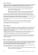
INTRODUCTION TO THE ORION AND ITS USES The Orion is a flexible unit designed to help you build point-to-point links and Base station-tomultiple-Outstation networks, carrying serial user data, telemetry information, or both. In simpler configurations, no additional equipment is required. Each unit contains a modem and a transceiver, which can be ordered according to the frequencies and range required.
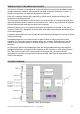
The Orion is a radio modem with on-board telemetry inputs and outputs. It also contains supervisory software which supports links and addressed networks. It is available in a number of different versions to suit different applications, and has many user-programmable features, which may be locally or remotely set. Figure 3 shows the Orion in block diagram form.
Part One - the Orion Unit 1892 1335 - Orion Radio Modem Operating Instructions - v2.
1892 1335 - Orion Radio Modem Operating Instructions - v2.
ORION MODES The Orion supports five modes of operation to enable you to build exactly the link or network you want. They are: v U - User Data only v R - repeater v I - independent (standalone) telemetry + User Data v E - externally-controlled telemetry + User Data v L - data logging Depending on the mode you select, other features become available. Addressing is available in all modes - see page 14. This section (pages 10 to 13) describes the network topologies and features of each mode.
Mode U - Data Only The Orion can be used as a high-performance data modem without using its built-in telemetry capabilities, and can be ordered without telemetry hardware at a saving in cost. Mode U supports half-duplex or simplex serial User Data communication via Serial Port A. Typically, two modems will communicate half-duplex, but other topologies are possible: v Using the address facilities of the Orion, many such pairs may share a frequency (on a time-sharing basis).
v One unit polls the other, volunteering its inputs, and the other replies with its inputs. Each then mimics the other’s inputs on its outputs. In either of these arrangements, alarms are sent spontaneously under predefined conditions unless suppressed, and are acknowledged by the other unit. See page 16. It is also possible to run a one-to-all topology in this mode, where the Base unit broadcasts its inputs regularly, and all other units duplicate them on their outputs.
Mode E - Externally-controlled Telemetry This mode is used where the inputs and outputs at many Outstations are individually interrogated and controlled by external SCADA equipment at a Base station. The Base unit relinquishes most of its functions to the SCADA equipment, which controls polling, input/output, acknowledgements, retries and alarm handling via Serial Port B. In order to do this, it must use the message protocol described in Appendix B on page 75.
Mode L - Data Logging Logging mode is used where equipment at many sites produces information, and there is a need to retrieve it periodically from a central location. At each site, an Orion Outstation stores serial data presented to Serial Port A, and relays it to the Base when it is polled. The Base polls addresses between one and the total number of sites, receiving the data and outputting it on Serial Port A which is connected to external logging equipment.
ADDRESSING In order that you can create systems containing two or more Orions, or even several separate systems, all on the same frequency, the Orion supports addressing. This works by having one or more groups each containing between two and 254 Orion units. Each Orion bears the number of a group to which it belongs, and its own unique number within that group. By including both IDs in a message, it is possible to identify the specific unit for which a message is intended.
v Group 0 messages are treated as broadcast, and are not acknowledged or replied to. Therefore they must not be used when Packet over-air protocol is used. v Repeaters ignore messages with GroupID 0. GroupID 255 is reserved for future use, and is not a permitted value at present. Identities can be set with the following commands (see p.63 for detailed information): ID GroupID UnitID DestID Set by ATS169 ATS170 ATS171 1892 1335 - Orion Radio Modem Operating Instructions - v2.
ALARMS AND ALERTS v Alarms and Alerts only apply where there are telemetry inputs and outputs, and therefore only to Modes I and E. An alarm is a state where an input has fulfilled a specified condition in terms of magnitude, logic state, time etc. which requires some action such as sending a message. An alarm can be raised, persist for a time, and then clear. There are two types in the Orion: v Telemetry alarms v Housekeeping alarms Telemetry alarms relate to telemetry inputs.
Alarm Parameters Raise conditions Comms Poll period time (0=off) (ATS183) and tolerable number n of missing messages (ATS184) Ack is not received to n polls (Base) or poll is not received within poll time Next poll is received + 3s for n consecutive periods (Outstation) Number of message attempts (alarm, spontaneous or poll) (ATS185) Acknowledgement is not received to the set A message is received number of consecutive from unit n. attempts to send a message to unit n.
Before going into failsafe mode, the unit transmits a message announcing that it will go into this mode unless a poll is received within a programmable time. If the poll is received, it responds in the usual way and goes back to normal operation. Otherwise it goes into failsafe mode. When the alarm clears again, the outputs stay as they are until a poll provides new output information. 18 1892 1335 - Orion Radio Modem Operating Instructions - v2.
SERIAL INTERFACE CONFIGURATION The Orion has no user-selectable switches or links, but is fully programmable via its serial data ports, using either the supplied Graphical User Interface described in Part Two of this manual, or the AT commands listed in Part Three. The serial ports are the same ones used during operation for User Data, SCADA and I/O. Serial port connections are shown on page 33, and port parameters below.
TELEMETRY CONFIGURATION There are three basic telemetry modes, MI, ME and ML, with variations as explained on pages 10 to 13. This section looks at the parameters which are common to several modes, and the parameters which are mode-dependent. Common Parameters (MI and ME) Analogue input scaling (four inputs, individually set) (ATS300n) 0-2.5V, 0-5V, 0-10V, 0-20mA* Digital input Low = closing contact or 0V High = open circuit or 3.
Unit ID (ATS170) The Base unit is defined by having UnitID set to 0, and is responsible for polling if applicable. For one-to-one configurations, set the single Outstation to UnitID = 1. Although Outstations in a one-to-all configuration are always addressed together using a broadcast code, they should be given separate Unit IDs from 1 up to 254 so that they can be separately addressed for maintenance or distinguished for User Data purposes. See the section on Addressing on page 14.
Mode E Parameters Unit ID (ATS170) The Base must have the UnitID 0 and is connected to the SCADA. The SCADA must insert UnitID 0 as the source in its messages so that replies are correctly routed on return. Outstations should be given Unit IDs from 1 up to 254, although they need not be contiguous.
Mode L Parameters Unit ID (ATS170) The Base is defined by being given the UnitID 0. Outstations should be given Unit IDs from 1 up to the number of Outstations, maximum 254, and must be contiguously numbered. Dest ID (Destination for messages which the unit initiates) (ATS171) During normal polling, this setting is ignored: the destination is dynamically controlled by the Base, and Outstation replies always go back to the sender. Group ID (ATS169) Grouping may be used as for the other modes.
USER DATA CONFIGURATION Some User Data configuration may be relevant in Modes I and E as well as U, because User Data may be carried beside telemetry in those modes. Mode U Parameters Unit ID (ATS170) The address of the unit. Since there is no distinction between Base and Outstation for Data Only, UnitID may be any value from 0 to 254 provided it is a unique address within the Group. Dest ID (ATS171) The UnitID of the unit which will receive the data, hence 0 to 254.
buffer is empty, which may either be because there is no more data, or, in the case of a slow source, because transmission has outstripped the input. If a further byte appears in the buffer, the process is repeated. When set to End of Message, the transmission sequence is triggered by a break in the User Data input. This may be because the message has ended, or because the sender has been flow-controlled to avoid buffer overflow.
REPEATER CONFIGURATION A repeater serves a single group, relaying User Data or telemetry messages which it receives without alteration of any kind. The group must use addressing (i.e. not GroupID 0). It prevents proliferation of messages by maintaining a list of messages already relayed, which it ignores. Broadcast messages with the DestID 255 are relayed, but messages with a GroupID of 0 are ignored. v All Orion units maintain a list of recently received messages, and discard duplicates.
RADIO CONFIGURATION A number of different radio modules may be fitted to the Orion for different bands, powers etc. As part of the test and setup routine at the factory, most of the radio parameters will be set up to suit the module fitted, although you can alter them if necessary with reference to Part Two of this manual or the AT Command Reference starting on page 63.
Protocol Selection TS is a basic half-duplex link for asynchronous serial data. It has no error correction. TU also provides a half-duplex asynchronous serial data link, but it has Feed-forward Error Correction (FEC) so that many errors can be corrected. TP provides a half-duplex asynchronous serial data packet link with both FEC and requests for repeat transmission of corrupt packets to provide an error-free link. v This protocol cannot be used in conjunction with a repeater.
OPTIONS WHEN ORDERING Many options are user-programmable, but the options below must be specified when ordering so that the correct version of the Orion can be supplied: OEM PCB version The Orion is available uncased as a PCB for mounting in OEM equipment. Modem Only version The Orion is also available as a straight radio modem without the telemetry in/out capability. Frequency band of operation The Orion can be supplied to operate in the VHF, UHF and higher (e.g. 868MHz) bands.
INSTALLATION Physical The cased version may be used freestanding or fixed using the four holes provided: Figure 7 - Orion (cased) dimensions and mounting (mm) Figure 8 - Orion (cased) clearance (mm) The PCB version should be mounted using the holes provided, and requires clearances as shown overleaf. 30 1892 1335 - Orion Radio Modem Operating Instructions - v2.
Figure 9 - Dimensions of Orion PCB (mm) Figure 10 - Required mounting clearances for Orion PCB 1892 1335 - Orion Radio Modem Operating Instructions - v2.
Connections Power Front panel, locking power plug, 2 pole with 2.1mm centre pin. Centre conductor: +9 to +15V DC Outer conductor: 0V (connected to unit ground) Antenna Female BNC, 50O (or as radio connector on PCB version) Antenna connection for both transmit and receive. The antenna will typically be mounted directly onto this connector; otherwise the connection to the antenna should be as short as possible and made in high-quality low-loss coaxial cable.
Serial Port A: User Data and AT Command interface RJ45 8-way female connector The interface is soft-configured to be RS232, RS422 or RS485 using command ATB2.
Earthing and Equipment Protection It is important that the unit be correctly earthed. Failure to do so makes it vulnerable to damage, especially where high-voltage equipment or voltage spikes are present. These points should be earthed to a common ground point: v The power supply negative output. Floating output power supplies are not suitable.
INDICATIONS DURING OPERATION Three LED indicators are visible on the front panel, with the following meanings. Red text in this section indicates a problem which needs attention. 1892 1335 - Orion Radio Modem Operating Instructions - v2.
TEST AND FAULT-FINDING FACILITIES The Orion offers a number of facilities for checking correct operation, using the GUI (Part Two of this manual) or AT commands (page 63). If all else fails, it is possible to restore a unit to its factory state.
GUI Status Messages When the GUI is connected, you can read the unit serial number, firmware release, PSU voltage and general status on the main window. The yellow message panel shows any messages. At connection, it should display “Searching for parameters.... modem parameters read OK!” If one or more errors exist, this will be displayed together with a single code number which you can give to Wood & Douglas technical support. Some possible errors are listed below.
Memory Parameters are stored in two different memory allocations, FLASH and EEPROM. When parameters are written to the unit using the GUI (not simply edited on-screen), both FLASH and EEPROM locations will be updated. When updating parameters using any AT-command, only the EEPROM is updated. If the parameters are not saved using the AT-save command (AT&W), the EEPROM parameters will be overwritten if the Orion is powered off and on again.
Part Two - the Graphical User Interface (GUI) 1892 1335 - Orion Radio Modem Operating Instructions - v2.
1892 1335 - Orion Radio Modem Operating Instructions - v2.
INTRODUCTION TO THE GRAPHICAL USER INTERFACE (GUI) The Orion GUI is a program which runs on a PC under Windows, and provides a simple and convenient way to set up local or remote units. It is connected to Serial Port B of the local or Base unit, and offers tools to manage (save, retrieve etc.) as well as to edit configurations. v The Orion can also be interrogated and controlled using your own equipment and software.
CONNECTING THE GUI TO AN ORION Ensure that the serial comms port of the PC which is used to run the GUI program is connected to the Orion Serial B port using a suitable cable as described on page 33. v If your computer has no serial port, you need to use your computer’s USB port and a serial-to-USB adaptor: see Appendix D on page 85, 86. The GUI must have been installed on the PC as described on page 41. Switch on power to the Orion.
Click on the COM port listed at the top left-hand corner to which you have connected the Orion, e.g. COM1. This should establish contact with the Orion, and the window appearance should change, with the message Modem Connected displayed. The unit’s details are uploaded to the GUI and some are displayed. Note that this overwrites any details that are currently held by the GUI.
CONFIGURATION MANAGEMENT Configuration management is carried out using menu commands. Editing of individual parameters is carried out in the main area of the GUI. File Menu - load and save configurations to disk v Any parameters currently being edited in the GUI are overwritten when a configuration is loaded. Load User Parameters Load user parameters from a file into the GUI editing window. Level2 and Radio parameters are not loaded as these are password protected.
Factory Settings Read Load all parameters (including passworded) from the Orion Factory Settings memory to the GUI editing window. Factory Settings Write Password protected. Write all parameters (only including passworded when passwords have been entered) from the GUI editing window to the Orion Factory Settings memory. Progress is reported onscreen, and the configuration is read back for verification. Factory settings are automatically written when programming the Orion at factory for the first time.
SERIAL INTERFACE PARAMETERS To change the parameters for either port of the Orion, select the values you want on the Serial Interface tab. Serial Port A can be set to many protocols, and is used for User Data. Serial Port B has relatively fixed protocols, and is used for configuration and telemetry (SCADA). Either port can be used for AT commands. When you have selected parameters, select Link > Write Parameters from the menu bar to write them to the Orion.
Addressing Section Addressing on page 14 explains the addressing scheme used by the Orion in detail. v If you intend to use no addressing at all, select the No Addressing checkbox and ignore the other addressing details. This is only available in Mode U. Remember that repeaters cannot be used in such a network. v If you intend to use a Broadcast topology, select the Master Broadcast checkbox for the Base unit and ignore the other addressing details.
Polling Poll timer unit is multiplied by the Poll timer time to allow times from 100ms to 182 hours (over a week). In Mode I, leaving this at zero enables Spontaneous Mode, which is not polled. Entering a time makes the Base poll with that frequency, and the Outstation expect a poll and raise an alarm if it is not received with that frequency. In Mode E, this parameter is ignored at the Base, because polling and acknowledgements are controlled by external equipment.
Analogue In/Out Configuration v These tabs apply to Modes I and E only. Figure 17 - Mode E Analogue Config tab on lower set Figure 18 - Mode I Analogue Config tab on lower set The Analogue Configuration tab sets the configuration of the four analogue input ports (ADC) and output ports (DAC). Range: The analogue input and output ports can be configured for 0-20mA, 0-2.5V, 0-5V or 0-10V, selected in an individual dropdown box for each port.
Analogue Alarms Figure 19 - Analogue Alarms tab on lower set Each input can transmit an alarm message back to the Base if certain conditions are met or exceeded. To generate an alarm, the level must go above or below (depending on the Trigger setting) the level entered into the Trip Level box for at least the time entered into the Dwell Time box. Dwell time is in units of 10ms, so for example one minute is represented by 100.
Digital Alarms Figure 21 - Digital Alarm tab on lower set Each input can transmit an alarm message back to the Base if certain conditions are met or exceeded. A normal digital input must make the transition indicated by the Trigger setting and remain there for at least the time entered into the Dwell Time box. This alarm can be turned on and off using the Counter Trip Level box: 0 means off, any other value means on. Dwell time is in units of 10ms, so for example one minute is represented by 100.
GENERAL PARAMETER CONFIGURATION Figure 22 - General Parameters tab Factory-set Parameters These parameters are to mainly do with the radio module used, and are set up in the factory. They require the Level 2 password to unlock them before they can be adjusted. Transmitter key-up time: This time in ms is allowed to elapse before any data is sent, to ensure that the radio is ready. The value depends on the particular radio fitted.
received, before regarding it as lost and a communications failure to exist. Equivalent to the ATIPRT command. Test Message Period: The time which is allowed to elapse in between transmissions of the test string in response to the ATI3 command, in tens of milliseconds. TX Priority: Don’t TX on busy channel: Normally, the Orion will not transmit if the squelch indicates that there is already a transmission on frequency. However, where there is interference, this box may be checked to transmit regardless.
Additional Logging Parameters When Mode L Base station is selected, additional parameters become available on the Parameters tab. Figure 23 - ML Base Parameters tab Poll timer unit (100ms, 1sec or 10sec) is multiplied by the Poll timer time to allow times from 100ms to 182 hours (over a week). This sets the time interval left between complete polls of all Outstations. For more detailed information, see pages 23 and 13. The Number of Outstations is the number which the Base station polls in its sequence.
RADIO FREQUENCY Figure 24 - Radio Frequency tab Select the Radio Frequency tab to set the operating frequency. The tab displays the radio type and TX and RX frequency. For convenience, the frequency is set by three drop-down lists containing valid channel frequencies within the radio bandwidth. The readout is in MHz. You do not need a password in order to set this parameter. The frequency does not change until you write the data to the unit using Link > Write Parameters from the menu bar.
RADIO PARAMETERS Figure 25 - Radio Parameters tab User Option Radio Power can be set to High or Low. The exact output depends on the radio module fitted. You do not need a password in order to set this parameter. Radio Parameters All other selections on this tab require the Radio Parameters password to be entered. These parameters should not need to be changed unless a new radio module is installed. Radio Module: the type of radio fitted.
DATA LOGGING USING THE GUI The GUI can store and display data and housekeeping information for a number of Outstations in ML mode. Click the Tools>Data Logging menu item, and the Data Logging window shown in Figure 26 will show. Figure 26 - Data Logging Window Data and alarm messages are displayed, and an option for file storage; store all data in one file or to a separate file for each Outstation.
TROUBLESHOOTING AND MAINTENANCE Firmware update If new Orion firmware version is available, the new release can be uploaded to the Orion FLASH memory. No additional equipment is required. Select Link > Firmware Update, select the new HEX firmware file in the dialog box, double click on it, and the update sequence will start automatically. The progress will be displayed in the yellow text box v Please wait until the programming sequence is finished before using the GUI again.
Engineering > TX Carrier, no timeout Engineering > TX Preamble, no timeout Engineering > TX Random Data, no timeout Only for use by W&D engineers. As above, but with no automatic timeout. Password protected. Stop TX Test The test in progress will be terminated and the Orion will go back to normal operation. Remote Tests The Remote Station ID must be entered in the field just above the yellow text area, either by typing it or selecting it from the drop-down list if this was used.
Figure 27 - Link Quality Monitoring Help The selection Troubleshooting > Technical support brings up an email addressed to Wood & Douglas technical support, containing a summary of information which will be useful in solving any problem. Help > Help Contents brings up online help. Help > About brings up information about the GUI. 60 1892 1335 - Orion Radio Modem Operating Instructions - v2.
Part Three - Appendices 1892 1335 - Orion Radio Modem Operating Instructions - v2.
1892 1335 - Orion Radio Modem Operating Instructions - v2.
APPENDIX A: AT COMMAND REFERENCE Normally the GUI is the best way to configure, control and interrogate a local Orion unit. However, if you want to use your own equipment and software to do this, you can use either of the serial ports to send ASCII AT commands and receive replies, which are listed in this Appendix. As is standard for AT commands, they are differentiated from data to be transmitted by sending a special code.
If any of these conditions is not fulfilled, then the string "+++" will be transmitted as normal data. Note that one or more consecutive “+” characters in the input data may be held in the unit until it is determined that it is not a Command Mode instruction. Command Syntax Once in Command Mode, commands are issued by sending codes consisting of ASCII characters. All commands start with the characters AT. Further characters are added to identify the particular command.
Leading zeros and the plus sign for positive values may be entered or omitted. Thus these strings are considered valid entries for a parameter shown as xxx: 1 01 001 +1 +01 +001 whereas 0001 is not (too many places). Where a number of places are shown after a decimal point, the decimal point must be entered, but no leading zero is required before the point, and not all the trailing spaces need be filled. Thus these strings are some of the acceptable entries for a parameter shown as xxx.xxxxxx: 0.0625 0.
The unit is now ready for normal data transmission, and if a new baud rate was set, it now comes into effect. A Note About Baud Rate The baud rate which you set on port Serial A and Serial B, using commands ATB0 and ATB3 respectively, applies both to User Data/telemetry commands and also to AT Command Mode. If you change the rate, it takes effect when you leave command mode (ATO). After this, you need to change the baud rate at the GUI or other terminal to suit before you can go back into command mode.
1892 1335 - Orion Radio Modem Operating Instructions - v2.9 / Aug 2009 AT Commands and Parameters Reference These tables are for firmware 08.03.05, Date: 09/03/2008. Enhancements may be made to the registers and parameters available in later versions..
Unit Supervision and Test Command Description Set Syntax 1892 1335 - Orion Radio Modem Operating Instructions - v2.9 / Aug 2009 Parameter Description ATS330=m Read Syntax ATS330? Master control of whether Outstation may initiate transmission (spontaneous, ack or alarm).
1892 1335 - Orion Radio Modem Operating Instructions - v2.9 / Aug 2009 Over-Air Parameters Read Parameter Description Value or Range Meaning of Values Default Syntax Value The following parameters are fixed properties of, or values appropriate to, the radio, which the system needs to know. Top of switching bandwidth ATFHB=xxxx.xxxxxxx ATFHB? xxxx.xxxxxxx Highest frequency Depends on radio Frequency in MHz Bottom of switching ATFLB=xxxx.xxxxxxx ATFLB? xxxx.
Description Command Set Syntax Operating Frequency AT&F=xxxx.xxxxxx x Over air protocol ATM0=pp No. of retries in TP mode Power level Over the air symbol rate Sync tolerance 1892 1335 - Orion Radio Modem Operating Instructions - v2.9 / Aug 2009 RX-TX priority User data queuing behaviour ATPRT=n ATS160=b ATS163=n ATS166=n ATS180=b ATMTX=n Read Syntax AT&F? Parameter Description xxxx.
1892 1335 - Orion Radio Modem Operating Instructions - v2.
Addressing and Polling Command Description Set Syntax Group ID Unit ID (sent as SourceID with over-theair messages) Destination ID Polling timer AND message initiation behaviour.
1892 1335 - Orion Radio Modem Operating Instructions - v2.9 / Aug 2009 Telemetry Input/Output Description Command Set Syntax Digital input n configuration ATS312n=p,t,d,s Read Syntax ATS312n? Parameter Description n p t Input number Pulse count or digital input Dig alarm enable/ Count to trigger alarm d Dwell time for digital alarm/ Dwell for spontaneous/ Min pulse width for count Trigger edge for dig alarm/ Trigger edge for count Input to use as PTT s Digital input n as PTT (i.e.
Description Command Set Syntax Dead band and dwell time for spontaneous reporting of analogue port n Read Analogue input n ATS304n=l,t Analogue output n h/w configuration ATS305n=m,f,e Analogue output n value 1892 1335 - Orion Radio Modem Operating Instructions - v2.
APPENDIX B: OVER-AIR COMMAND CODES Normally the GUI is the best way to configure, control and interrogate a remote Orion unit. However, if you want to use your own equipment and software to do this, you can use the serial port of the local Orion to send over-air commands and receive corresponding replies, which are listed in this Appendix. Summary of Messages and Responses The table below summarises the message codes used over the air between the Base station and the Outstation.
Message Syntax 04 = Prefix byte marking start of all messages IDS = A byte containing the ID number 0-254 of the source in binary IDD = A byte containing the ID number 0-254 of the source in binary Note that Base station will always be ID = 0 aa = 1 byte data (a can be any letter) aaaa = 2 byte data (a can be any letter) CH = CHECKSUM: additive sum of bytes in message where CH is the low order byte of the sum of all the bytes in the message, apart from the first three. I.e.
1892 1335 - Orion Radio Modem Operating Instructions - v2.9 / Aug 2009 Description Set Read Syntax Base Command Outstation Reply Base Command Outstation Reply Poll Outstation (“Are you there?” and battery level). 04 IDS IDD 20 CH 04 IDS IDD 50 bbbb CH - - Level: byte bbbb contains a value 0 to 1023, where 0 = 0V and 1023 = 20.
Description Set Read Syntax Base Command Outstation Reply Base Command Outstation Reply Digital inputs - - 04 IDS IDD 41 CH 04 IDS IDD 71 nn CH State: byte nn bits 0 to 3 represent ports 1 to 4 respectively. Value 0 = Low, 1 = High Set digital outputs (all ports) 04 IDS IDD 24 nn CH 04 IDS IDD 54 nn CH 04 IDS IDD 48 CH 04 IDS IDD 78 nn CH State: byte nn bits 0 to 3 represent ports 1 to 4 respectively.
1892 1335 - Orion Radio Modem Operating Instructions - v2.9 / Aug 2009 Description Set Read Syntax Base Command Outstation Reply Base Command Outstation Reply Analogue input levels - - 04 IDS IDD 40 CH 04 IDS IDD 70 mmmm, nnnn, oooo, pppp CH Level: bytes mmmm, nnnn, oooo, pppp represent ports 1 to 4 respectively. Value 0 to 1023 represents proportion of full scale output.
Description Set Base Command Outstation Reply Read Base Command Syntax Outstation Reply Alarms initiated by Outstation (expecting ack 04 IDS IDD 16 CH from Base station) Announce entry into Failsafe state - - - 04 IDS IDD 67 CH To stop the outstation proceeding into failsafe state, the base station must poll it with any valid command. Digital input alarm (Outstation initiates) - - - 04 IDS IDD 91 bb CH State: byte bb bits 0 to 3 represent ports 1 to 4 respectively.
APPENDIX C: ATT? PARAMETER STRING STRUCTURE The Orion responds to the ATT? command by returning the data which could be obtained by issuing all the read commands (those ending in a question mark). It is chiefly intended to be read by a computer, and is therefore presented with few annotations. The data is presented as a number of strings separated with , and each string consists of a series of comma-separated fields. In some cases, several fields correspond to a single AT register.
32 33 34 35 36 37 38 39 40 41 42 43 44 45 46 47 48 49 50 51 52 53 54 55 56 57 58 59 60 61 62 63 64 65 66 67 68 69 70 71 72 73 74 75 76 77 78 79 80 81 82 82 ATS165 ATS166 ATS156 ATS158 ATS169 ATS170 ATS171 ATS172 ATS172 ATS172 ATS172 ATBL ATPRT ATPT ATS180 ATS173 ATS189 ATS330 ATS336 ATS337 ATS184 ATS185 ATS183 ATS183 ATS188 ATS310 ATS316 ATS3041 ATS3041 ATS3042 ATS3042 ATS3043 ATS3043 ATS3044 ATS3044 ANALOGUE INPUT 1 ATS3001 ATS3011 ATS3021 ATS3021 ATS3021 ANALOGUE INPUT 2 ATS3002 ATS3
84 85 86 87 88 89 90 91 92 93 94 95 96 97 98 99 100 101 102 103 104 105 106 107 108 109 110 111 112 113 114 115 116 117 118 119 120 121 122 123 124 125 126 127 128 129 130 131 132 133 ANALOGUE INPUT 3 ATS3003 ATS3013 ATS3023 ATS3023 ATS3023 ANALOGUE INPUT 4 ATS3004 ATS3014 ATS3024 ATS3024 ATS3024 ANALOGUE OUTPUT 1 ATS3051 ATS3051 ATS3051 ATS3061 ANALOGUE OUTPUT 2 ATS3052 ATS3052 ATS3052 ATS3062 ANALOGUE OUTPUT 3 ATS3053 ATS3053 ATS3053 ATS3063 ANALOGUE OUTPUT 4 ATS3054
134 135 136 137 138 139 140 141 142 143 144 145 146 147 148 149 150 151 152 ATS3142 ATS1812 DIGITAL INPUT 3 ATS3123 ATS3123 ATS3123 ATS3123 ATS3143 ATS1813 DIGITAL INPUT 4 ATS3124 ATS3124 ATS3124 ATS3124 ATS3144 ATS1814 Read digital input 2 state Pulse count at digital input 2 (no reset) [new line] [Literal-text annotation] Digital input 3 pulse or digital Digital input 3 alarm enable/count Digital input 3 dwell time or min pulse width Digital input 3 trigger direction Read digital in
APPENDIX D: SERIAL TO USB ADAPTOR Some laptops and PCs are no longer supplied with RS232 serial ports; in this case, a USBto-RS232 adaptor can be used to connect the PC running the GUI to the Orion. Wood & Douglas have tried a range of adaptors and recommend the EasySync US232B/LC, which has been tested with Windows 2000 and Windows XP. v Further information and a downloadable manual can be found at www.easysync.co.uk/usbrs232_single.html.
APPENDIX E: SPECIFICATIONS Versions Radio modem with telemetry, user data or both Power supply External 9 to 15V DC, 0V earthed (not a floating supply) <100mA RX, <1000mA TX (1W RF out) Front panel connection via locking 2.1mm power plug. Earthing Unit chassis, supply negative, antenna screen, data ground and telemetry ground connections should be earthed to a common point external to the unit. Over-air data rates 19200 baud (20 and 25kHz channel width), 9600 baud (12.
User data rates Depends on over-air rate and transmission mode / packet size chosen. Can be calculated as follows: Message overhead: 50 bytes FEC takes 28% of remaining (non-header) bytes if used. Packet Mode overhead: 52 bytes per message (plus wait for 50 byte acknowledgement). 1024 byte maximum length.
APPENDIX F: DIN RAIL MOUNTING ACCESSORIES There are two types of DIN rail adaptor which can be used to bring out the inputs and outputs of the Orion at a DIN rail. (An adaptor is also available to mount the Orion unit itself on a DIN rail, not shown here.) Each adaptor is connected to the Orion via an 8-way male RJ45 to male RJ45 cable wired pin-to-pin. LED indicators are provided (see text). 88 1892 1335 - Orion Radio Modem Operating Instructions - v2.
Digital Inputs, Analogue Inputs, Analogue Outputs: Adaptor 01146 0200 A Digital inputs: connect to Port 2 on the Orion Analogue inputs: connect to Port 3 on the Orion Analogue outputs: connect to Port 4 on the Orion Connector pins are used as follows: Pin No.
Digital Outputs: Adaptor 01146 0201 A Digital outputs and Alert: connect to Port 1 on the Orion Connector pins are used as follows: Pin No. Port 1 Digital Out Ports 2 - 4 Digital In / Analogue Alert option A1 B1 A2 B2 A3 Open collector N.C. no connection COM no connection N.O. output As B1 As B1 Digital Out 1 COM B3 A4 Digital Out 1 N.O. Digital Out 1 N.C. B4 A5 Digital Out 2 COM Use adaptor 01146 0200 A Digital Out 2 N.C. B5 A6 Digital Out 2 N.O. Digital Out 3 N.C.
Notes: This adaptor converts all four digital outputs to floating SPDT relay contacts. The Alert output is a relay or open-collector output, depending on how the unit was ordered, and is not converted. If the Alert output is to be used, and is an open collector output, the 0V return is via PL1. If LED indication is required when an output is in its energised state, 12V at up to 40mA must be provided via connector PL1, which may be taken from the same supply as the Orion.