
Specifications
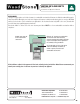

Mountain Series
Installation and Operation Manual
An ongoing program of product improvement may require us to change
specifications without notice. WS-MS-(4,5,6,7)-RFG-W,
Revised May 2015. Doc no: M0032.02
info@woodstone-corp.com or visit woodstone-corp.com
wood stone corporation
1801 w. bakerview rd.
bellingham, wa 98226 usa
tf. 800.988.8103
t. 360.650.1111
f. 360.650.1166
26
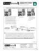
ASSEMBLY
1. Mount the oven mantle (if provided) using the hardware provided� Please refer to the MANTLE MOUNTING section�
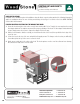
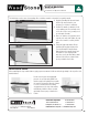
2. Mount the stainless steel toe kick to the front of the oven stand, angle side down using the large self tapping screws�
The holes are pre-drilled in the stand� If your oven is equipped with a Service Panel extension or storage box, a toe
kick is not necessary� Refer to assembly diagrams in the pages that immediately follow�
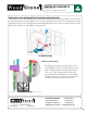
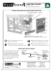
3. Mount the service/intake panel to the brackets on the front of the stand, directly below the doorway, using the screws
provided� See the FRONT PANEL ASSEMBLY section� If your oven was shipped with the optional facade extensions,
see EXTENSION PANEL ASSEMBLY section�
NOTE: This panel is the only access for servicing the gas and electrical components of the oven so it must be
left accessible and removable� Do not obstruct the flow of combustion and ventilation air through the perforation
provided on the front panel�
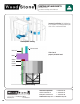
4. The following applies to stucco finish ovens only (models ending with “-S”): Once the oven has been set in place,
cover wire mesh and metal lathing with no less than 1 inch of stucco (see STUCCO APPLICATION section for diagram
and stucco formula)�