
Specifications
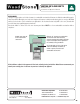

Mountain Series
Installation and Operation Manual
An ongoing program of product improvement may require us to change
specifications without notice. WS-MS-(4,5,6,7)-RFG-W,
Revised May 2015. Doc no: M0032.02
info@woodstone-corp.com or visit woodstone-corp.com
wood stone corporation
1801 w. bakerview rd.
bellingham, wa 98226 usa
tf. 800.988.8103
t. 360.650.1111
f. 360.650.1166
29
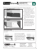
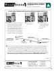
EXTENSION PANEL ASSEMBLY
OPTIONAL LOWER EXTENSION, THROTTLE ROD AND CONTROLLER ASSEMBLY INSTRUCTIONS
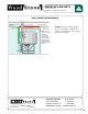
1. After the oven has been leveled, remove
the Extension Panel Throttle Assembly
which has been attached to the inside
of the stand for shipping� Position the
Lower Extension Assembly onto the front
of the oven� It will rest on the guides
that are welded to the oven legs� Attach
the assembly to the oven legs using the
supplied 1/4-20 nuts, bolts and washers�
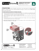
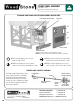
2. Remove the Front
Access Panel�
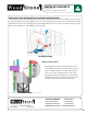
4. Remove the Flame Height Control Knob & Pointer Assembly from the Throttle Assembly� Slip the Clamp off
of the Throttle Knob Assembly and slide it over the EMT throttle rod extension� Slip the front of the EMT
Throttle Rod through the Throttle Rod Bracket at the front of the oven, then slip the other end of the EMT
onto the Throttle Valve at the back of the oven� Note: The end of the EMT that goes over the Throttle Valve
is drilled to accept a Cotter Pin� Attach the EMT Throttle Rod Extension to the Throttle Valve using the Cotter
pin and open the end of the pin slightly to prevent it from falling out� Make certain the valve is in the full
OPEN position by turning the attached Throttle Rod Extension counterclockwise until it stops.
Continued
3. Attach the Controller
to the mounting bracket
of the Extension using
the 1/4-20 bolts
provided�
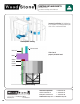
Flame Height Control
(Throttle) Knob
Throttle Bracket
(Attached to Extension)
Pointer Assembly:
Pointer & Pointer Collar
Clamp
EMT Throttle
Rod Extension
Throttle Valve
Cotter Pin
Extension Panel
Throttle Assembly