
Specifications
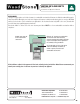

Mountain Series
Installation and Operation Manual
An ongoing program of product improvement may require us to change
specifications without notice. WS-MS-(4,5,6,7)-RFG-W,
Revised May 2015. Doc no: M0032.02
info@woodstone-corp.com or visit woodstone-corp.com
wood stone corporation
1801 w. bakerview rd.
bellingham, wa 98226 usa
tf. 800.988.8103
t. 360.650.1111
f. 360.650.1166
30
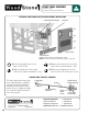
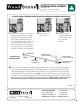
EXTENSION PANEL ASSEMBLY
OPTIONAL LOWER EXTENSION, THROTTLE ROD AND CONTROLLER ASSEMBLY INSTRUCTIONS
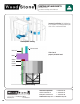
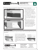
7. CALIBRATING THE POINTER
Loosen the Pointer Collar Set Screws using a 3/16"
Allen wrench� Position the attached Pointer to “5” on the
Flame Height Index Scale� Tighten the Pointer Collar in
this position� Make certain the tip of the Pointer is at least
1/8" away from the Index Scale at the tightest point of
the rotation of the Knob so it does not scrape�
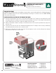
5. Pass the Throttle Rod through the Throttle Bracket (already attached)� Position
the Pointer in approximately the 2 o’clock position� Slide the Clamp on the EMT
over the end of the Throttle Rod/Knob assembly and attach the Throttle Rod to the
EMT Throttle Rod Extension using the compression Clamp (5/16" nut)� On curved
Facade Extensions, make to leave at least 1/8" of space between the end of the
Pointer and the Bracket when it is set to a horizontal position�
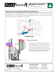
6. Reinstall the Front Panel� Secure the Controller with a 1/4-20 screw at the top
and bottom�
Use (2) #10 stainless steel sheet metal screws to secure the Front Panel to the
Throttle Bracket�
Pointer
Collar Set
Screws
1/8"
minimum
clearance
between
Pointer &
Bracket