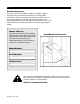
operator's manual INCLUDES SERVICE INFORMATION MODEL 8000 & 8100 CHIPPER PN-51210 (Rev.
W O O D S Dear Woods Customer, Thank you for purchasing a Woods Chipper. The Woods Chipper is designed, tested, and manufactured to give years of dependable performance. To keep your chipper operating at peak efficiency, it is necessary to adjust it correctly and make regular inspections. The following pages will assist you in the operation and maintenance of your machine. Please read and understand this manual before operating the chipper.
C O N T E N T S Contents Safety Instructions .............................................................. 2 Safety Decals ............................................................................. 6 Assembly ........................................................................... 7 AttachChipperChute ................................................................... Attach Chute Extension Tray ......................................................... Attach Blower Discharge Tube ................
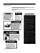
S A F E T Y I N S T R U C T I O N S Safety Instructions This chipper is designed and tested to offer reasonably safe service. Failure to operate it in accordance with the following safety instructions MAY RESULT IN PERSONAL INJURY! A safety message alerts you to potential hazards that could hurt you or others. Each safety message is proceeded by one of three words: DANGER, WARNING, or CAUTION.
S A F E T Y I N S T R U C T I O N S • Visually check that all screws, nuts, bolts, and other fasteners are properly secured before starting the machine. Check all screws, nuts, bolts, and other fasteners once every 10 hours of operation for proper tightness to insure everything is in proper working condition. • Empty the cutting chamber before starting the machine. • Exclude pieces of metal, rocks, bottles, cans, and other foreign objects when feeding chipable material into the machine.
SA F E T Y I N S T R U C T I O N S • Put transmission in neutral or park and disengage before starting tractor. WARNING: This chipper is designed to be used with tractor PTO's rated at 20 to 60 horsepower. Using this chipper with PTO's above 60 horsepower may cause belt and machine damage in overload conditions. Additional Safety Rules for PTO Models PN-51210 (Rev. 7/98) 4 • Stay alert and pay attention when PTO chipper is operating.
S A F E T Y I N S T R U C T I O N S • Keep hydraulic hoses, electric cords, chains, and other items from contacting the driveline. • Make sure transmission is in neutral or park and PTO is disengaged before starting the tractor. • Do not exceed the recommended 540 RPM PTO operating speed. • Disconnect PTO and shut off tractor when this unit is stopped for servicing, inspection, storage, or to change an accessory. • Shut off the PTO, lift 3 pt.
SAFETY DECALS Safety Decals Safety and instruction decals are located on the chipper frame and engine. Replace any damaged or unreadable decal. NOTE: See parts drawings and lists for location of safety decals on the chipper frame. PN 57835, French Safety Decal Kit PN 51284 PN 51361 PN 51281 PN 51373 PN 51375 PN 51312 PN-51210 (Rev.
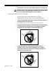
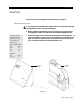
A S S E M B L Y Assembly For instructions on assembling the hydraulic feed kit, see page 20. Attach Chipper Chute Do not operate this unit without the chipper chute correctly installed. Rotating cutting blades can cause serious personal injury. 1. Remove chipper from shipping crate. Place unit on a level surface before attempting to assemble. See torque chart for minimum tightening torque. Torque Chart Standardminimum tightening torque for normal assembly applications. 2.
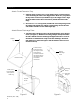
A S S E M B L Y Attach Chute Extension Tray 1. Slide the chute extension tray over the chipper chute as shown in figure 2 after mounting the chute to the chipper frame. Make sure you position the lip on the extension tray behind the lip on the chipper chute. Align the five bolt holes in the chute extension tray with the bolt holes in the hinge. 2. Insert five 3/8" x 1" carriage bolts (included in owners kit packaged with the chipper) through the tray and the extension hinge.
A S S E M B L Y Connect the Hydrostatic Control Cable (For models with factory installed hydraulic feed.) 1. Remove the clevis assembly from the hydrostatic control cable end (see figure 4). Remove one nut on the cable end. Insert the cable end into the hole in the cable anchor weldment. Replace the nut and the clevis assembly. 2. Attach the clevis assembly to the center hole on the feed control lever. 3.
CONTROLS Controls (see figure 5) 1. Three pt. Hitch Connection: Mounts chipper to tractor 3 pt. hitch. Connect direct for category 1. 2. PTO Shaft: Connects chipper to tractor PTO shaft. Avoid driveline angles over 20 degrees on PTO shaft when unit is in use. 3. Drive Belt Shield: Never remove shield while machine is running. 4. Chipper Chute: Feeds materials to the chipper blades for chipping. 5. Leg Stands: Never move machine unless legs are in UP position and clear the ground. 6.
O P E R A T I O N Operation CAUTION: Wear safety glasses at all times when operating the machine. Do not wear loose fitting clothing. The operator should always wear heavy boots, gloves, pants, and shirt. Use common sense and practice safety to protect yourself from branches, sharp objects, and other harmful objects. NOTE: The heavy rotor continues to turn for some time after the tractor has been shut off. The rotor is stopped when no noise or machine vibration is present.
O P E R A T I O N Chipping WARNING: Keep face and body away from the feed opening. Do not over reach. Keep proper balance and footing at all times. The Woods chipper is designed to chip a variety of materials into a more readily decomposing or handled condition. The following guidelines can be used to help you get started. Please read and follow all safety instructions in this manual.
SERVICE A N D M A I N T E N A N C E S C H E D U L E Service and Maintenance Schedule Before Each Use Inspection Items Every 10 Hours Every 25 Hours Every 50 Hours Interval Every Every 100 200 Hours Hours Every 300 Hours Every 800 Hours Every 1 years Check Nuts & Bolts (Entire machine) Check Replace Check Hydraulic Filter Element Clean * Replace Check Hydraulic Control Cable Check Sharpness of Chipper Blades Grease Bearings and Pivots Check Bolts: Chipper Blade, Chipper Anvil, Rotor Paddl
SERVICE AND MAINTENANCE Service and Maintenance WARNING: Shut off PTO and make sure all moving parts have come to a complete stop before inspecting or servicing any part of the machine. The chipping blades are sharp! Use care when working on machine to avoid injury. WARNING: The rotor assembly has a lock mechanism. Use the lock mechanism at all times when working on the rotor assembly. Remove plastic bearing cover under chipper chute.
S You do not have to remove the rotor from the main frame to repair the chipper blades or paddles located on the back of the rotor assembly. E R V I C E A N D M A I N T E N A N C E sharpened by a professional. Be careful when grinding if using a bench grinder so the blade material does not get too hot and change colorthis will remove the blade's special heat treated properties. Use short grinding times and cool with water. Remove an equal amount off each blade to maintain balance.
SERVICE A N D MAINTENANCE Adjusting or Replacing Drive Belts Check the condition of the drive belts annually or after every 30 hours of operating, whichever comes first. Replace cracked, frayed, or worn belts. Proceed as follows to replace or adjust the drive belt: 1. Disengage PTO and shut off tractor engine. 2. Remove PTO shaft from tractor; disconnect machine from 3 pt. hitch. 3. Remove round shield connected to belt guard covering the PTO shaft by removing two 5/16" nuts. 4.
S E R V I C E A N D M A I N T E N A N C E Repairing or Replacing Rotor Bearings 1. Remove two 3/8" retaining bolts holding access cover to main frame assembly. Tilt access cover over to allow rotor access. 2. Remove large belt guard (three 5/16" bolts). 3. Loosen bolts on hydraulic pump and remove hydraulic pump belt. Remove the bushing and pulley from the rotor shaft using the push bolts from the bushing. 4. Lift belt idler pulley off drive belt and remove belt from pulleys.
SE R V I C E A N D M A I N T E N A N C E Important! Check the bolts on the following for correct torque (75 ft. lbs.) every 10 hours of operation: Hydraulic feed roller bearing Hydraulic motor mounting Chipper rotor bearing Chipper blades Rotor paddles Chipper anvil Warning: Failure to maintain proper fastening torque (75 ft. lbs.
HYDRAULIC FEED INSTALLATION Hydraulic Feed Installing the Optional Hydraulic Feed Kit (For models without factory installed hydraulic feed.) Install the Roller Assembly 1. Remove the bolts fastening the chipper chute to the rotor housing weldment. 2. Remove the chipper chute mounting plate. 3. Hold the roller assembly up to the rotor housing weldment. Secure the roller assembly with 3/8" x 1-1/2" bolts, washers, and nuts. 4.
HYDRAULIC FEED INSTALLATION Install the 6.6" Pulley 1. Remove the chipper drive belt guard. 2. Put the 6.6" pulley on the rotor shaft end. 3. Place the 1.75" bushing on the rotor shaft and put the 3/8" x 1/4" key into the bushing slot. Do not tighten the bushing yet. Mount the Hydrostatic Pump 1. Attach the pump control arm to the pump control on the hydrostatic pump with two 1/4" x 1/2" bolts. 2.
HYDRAULIC FEED INSTALLATION 2. Thread the cable end into the cable pivot pin. Insert the pivot pin into the hole in the pump control arm. Secure the pivot pin with a 1/4" washer and a 3/32" x 3/4" cotter pin. 3. Place the cable clamp shim and clamp on the cable exterior (as shown on page 20). Secure the cable, clamp, and shim to the cable attachment angle with two 1/4" x 3/4" bolts and locknuts. 4. Remove one nut on the opposite cable end. Insert the cable end into the hole in the cable anchor weldment.
HYDRAULIC FEED OPERATION INSTRUCTIONS Hydraulic Feed Operating Instructions Fluids Handle pressurized hydraulic fluid carefully. Escaping pressurized hydraulic fluid has sufficient force to penetrate skin causing serious injury. This fluid may also be hot enough to burn. Serious infection or reactions can develop if proper medical treatment is not administered immediately. Premium hydraulic fluids containing high quality rust, oxidation, and foam inhibitors are required.
HY F D R A U L I C E E D OP E R A T I O N I N S T R U C T I O N S Control Arm Operation 1. Engage the PTO. Bring the chipper up to operating speed. See the operation section for starting, operation, and stopping instructions. 2. Engage the hydraulic feed by moving the control arm as shown in figure 11 below. The feed rate increases as the arm is moved in the forward direction. 3. Feed the branch (up to eight inches in diameter). 4.
HYDRAULIC FEED M A I N T E N A N C E Hydraulic Feed Maintenance NOTE: Check the reservoir daily for proper fluid level, the presence of water (noted by a cloudy to milky appearance or free water in bottom of reservoir), and rancid fluid odor (excessive heat). The hydrostatic pump normally does not require regular fluid changes. Change the system filter at 250 hour or annual intervals.
T R O U B L E S H O O T I N G Troubleshooting Problem Probable Cause Suggested Remedies Reference 1. Rotor does not turn a) Obstructed discharge. a) Use branch or similar object to clear discharge. b) Clear rotor. Service and Maintenance a) Use branch or similar object to clear discharge. b) Sharpen blades. c) Adjust clearance. Service and Maintenance a) Use branch or similar object to clear discharge. b) Clear rotor, feed material into shreddermore slowly.
CHUTE AND ROTOR ASSEMBLY PARTS LIST Chute and Rotor Assembly Part List No. Part No. 1. 2. 3. 4. 5. 6. 7. 8. 9. 10. 11. 12. 13. 14. 15. 16. 17. 18. 19. 20. 21. 22. 23. 24. 25. 26. 51458 51474 51459 51460 51464 51461 51462 51463 51682 51982 51506 51507 51557 51467 51468 51469 51472 51473 51470 51471 51554 51373 51374 51375 51361 51284 12650 Description Qty.
CHUTE AND ROTOR ASSEMBLY DIAGRAM Chute and Rotor Assembly Diagram PN-51210 (Rev.
CHIPPER BASE ASSEMBLY Chipper Base Assembly Diagram Chipper Base Parts List No. Part No. 1. 51505 2. 51465 3. 51466 4. 51475 5. 51570 6. 51273 7. 81286 8. 51314 9. 51234 10. 51224 11. 51315 Description Assy, Chipper Bottom Jackshaft, Chipper Drive Weldment, PTO Stand Hitch Support Weldment Spacer, RH Bearing, 2 BLT FLG 1-1/2" Bore Pulley, Idler 5" X 2.50" Sheave, 3B 13.6 SK Sheave, 3B4.8 SD Bushing SK1.5 Belt, BX 64 (Matched Set of 3) PN-51210 (Rev. 7/98) 28 Qty. 1 1 1 1 1 2 1 1 1 1 1 No. 12. 13.
CHIPPER No. Part No. 23. 51405 24. 51508 25. 51322 26. 51419 27. 51480 28. 51490 29. 51503 30. 51504 31. 3379 32. 3699 33. 1637 Description Qty. Spacer, .75 X 1.18 1 Assy, Upper Belt Guard & Decal (17) 1 Bushing, SD 1-3/4" 1 Joint Shield Weldment 1 Weldment, Idler Arm 1 Cover, Hose Access 1 Shield, Shaft 1 Plate, Spring Anchor 1 Bolt 1/2 X 1-1/2 GR5 Hex Capsw Zp 9 Bolt, 1/2 X 2 GR5 Hex Capscrew Zp 10 Bolt, 1/2 X 3-1/2 GR5 HCS ZP 1 No. 34. 35. 36. 37. 38. 39. 40. 41. 42. 43. 44. 45. 46. Part No.
HYDRAULIC FEED ASSEMBLY DIAGRAM Hydraulic Feed Assembly Diagram PN-51210 (Rev.
HYDRAULIC FEED ASSEMBLY DIAGRAM PN-51210 (Rev.
HYDRAULIC FEED PARTS LIST Hydraulic Feed Parts List No. 1. 2. 3. 4. 5. 6. 7. 8. 9. 10. 11. 12. 13. 14. 15. 16. 17. 18. 19. 20. 21. 22. 23. 24. 25. 26. 27. 28. 29. 30. 31. 32. 33. 34. 35. 36. 37. 38. 39. 40. 41. Part No.
S P E C I F I C A T I O N S Specifications Model 8000 Model 8100 Height (to discharge) 87" 87" FrameWidth 38" 38" FrameLength 36" 36" Overall Size 45" x 47" x 90" 45" x 47" x 90" Chute Size 32" x 36" 32" x 36" Frame Material 0.25" + 0.38" Steel 0.25" + 0.38" Steel Feed System Self Feed Hydraulic Discharge Blower Blower Maximum Chipper Capacity (dia.) 8" 8" Chipper Blade Qty. (*=tool steel) 4 Tool Steel 4 Tool Steel Rotor Speed 1500 RPM 1500 RPM Rotor Size 30" Dia. x 1.
Warranty Woods warrants each new Woods products to be free from defects in material and workmanship. This warranty is applicable only for the normal service life expectancy of the machine or components, not to exceed twelve consecutive months from the date of delivery of the new Woods product to the original purchaser. Genuine Woods replacement parts and components will be warranted for 90 days from date of purchase, or the remainder of the original equipment warranty period, whichever is longer.
HEALTH WARNING GASOLINE, DIESEL, AND OTHER PETROLEUM PRODUCTS Harmful or fatal if swallowed. Long-term exposure to vapors has caused cancer in laboratory animals. Avoid prolonged breathing of vapors. Keep face away from nozzle and gas tank/container opening. Never siphon by mouth. Failure to use caution may cause serious injury or illness.