
Company Brush Cutter User Manual

Assembly 43
MAN0963 (2/16/2012)
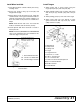
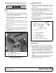
Install CV Drive (Optional)
Before installing cutter input driveline to gearbox, check
the tag wired to the driveline and the tag wired to the
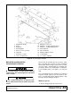
input shaft of gearbox. Ensure the tag rpm speeds
match the rpm speed decal on front of cutter. After con-
firming all speeds match, remove and discard tags and
then complete driveline assembly.
1. Align hole in drive yoke with groove on gearbox
input shaft and slide rear half of drive (23) onto
shaft.
2. Secure with bolt and nut supplied with drive.
Figure 32. CV Drive Installation
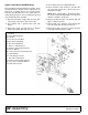
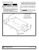
Install Wing
Use a suitable lifting device of sufficient capac-
ity. Use adequate personnel to handle heavy com-
ponents.
The wing must be installed in the following sequence
and will require at least two people. A floor jack or a
suitable lifting device will be helpful to align decks when
installing the hinge pin.
Check RPM tags on wing and center section to make
sure they match before proceeding.
1. Remove hinge pin (15) from center section.
2. Place wing assembly adjacent to the center section
and align hinge sections.
3. Insert hinge pin through the hinge sections and
secure with spring pin (64) and washer (107) on
both ends.
4. Attach side skid (6) to the wing using four carriage
bolts (81) and flange lock nuts (88).
5. Repeat procedure of opposite wing. (BW126XHDR
only had right wing installed. BW126XHDL only
has left wing installed.
Figure 33. Right Wing Installation
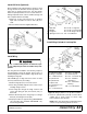
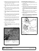
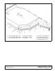
Install Wing Cylinder & Lock-up Bar
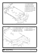
Figure 34. Wing Cylinder & Lock-Up Bar Installation
1. Place two cylinder links (19 & 20) on either side of
cylinder lug on center section as shown, align
holes and insert clevis pin (18).
NOTE: Items 19 & 20 must be installed with square
corners on top and facing cylinder as shown.
5. CV Drive
CAUTION
6. Side skid
8. Winglet
15. Hinge Pin
64. Spring Pin 1/4 x 1-1/2
80. 1/2 NC x 1 Crg Bolt
81. 1/2 NC x 1-1/2 Crg Bolt
88. 1/2 NC Flnge Lock Nut
107. 1" Flat Washer
4. Hydraulic Cylinder
16. Wing Lock-Up Bar
18. 1 x 4.08 Clevis Pin
19. Cylinder Link
20. Cylinder Link
21. Spacer, 3/4
22. Lock-Up Pin, 1 x 5
53. Spacer, 1"
54. 1 x 2.72 Clevis Pin
59. 1/4 x 1/4 x 200" Hose
61. 3/16 Safety Pin
62. 1/4 x 1-1/2 Cotter Pin
69. 1/4 x 1/4 Elbow
w/Restrictor
90. 1/2 x 1/4 Reducer
Bushing
108. 1 x 1-7/8 Washer