
Company Brush Cutter User Manual


Parts 81
MAN0963 (2/16/2012)
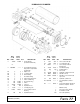
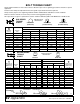
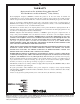
WINCH KIT (OPTIONAL)
REF PART QTY DESCRIPTION
A 1019456 - Winch kit, complete
1 52478 4 Idler bracket
2 6696 2 Chain idler casting
3 409 2 Clevis pin, 1/2 x 2
4 22411 2 Klik pin, 3/16 x 1
5 3379 * - HHCS, 1/2 NC x 1-1/2 GR5
6 11900 * - Lock nut, 1/2 NC flanged
7 1863 * - Washer, 1" SAE flat
8 1008325 2 Headless pin, 1 x 4 drilled
9 1266 * - Cotter pin, 3/16 x 1-1/2
10 1019454 2 Channel. 2.56 x 2.75 x 32.88
11 1019455 1 Channel, 3.12 x 3.25 x 10.00
12 12612 1 Gear winch 5.1 to 1
13 12642 1 Winch cable clamp kit
14 11790 1 C-Hook, 1/4 cable
15 52479 1 Cable, 1/4" x 24-ft
16 11789 2 Clip, 1/4 cable
17 839 * - HHCS, NC x 1 GR5
18 565 * - Washer, 3/8 flat
19 838 * - Washer, 3/8 lock
20 835 * - Hex nut, 3/8 NC plated
* Standard hardware; obtain locally
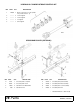
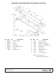
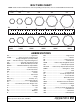
Winch Kit Installation
1. Locate and drill one 9/16" hole in each wing as
shown. Assemble items 1, 2, 3 and 4 and use to
locate and drill remaining holes.
2. Secure idler brackets (1) and rollers (2) to deck
with bolts (5) and nuts (6).
3. Assemble channels (10) to cylinder lugs using
pins (8), washers (7), and cotter pins (9) as
shown.
4. Assemble winch assembly to channels (10) using
bolts (5) and lock nuts (6).
5. Move SMV sign and hardware to channel as
shown.
6. Tighten all hardware.
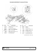
Winch Kit Operation
1. Move cutter so wing is on the up slope of a ditch
to aid in wing lift with the winch.
2. Unwind cable and remove roller (2).
3. Place cable around roller (2) and reinstall using
pin (3) and Klik pin (4).
4. Remove cylinder pin from clevis end and raise
slowly.
5. Install transport lock before moving unit.