
Company Brush Cutter User Manual

30 Dealer Service
MAN0963 (2/16/2012)
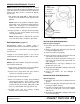
GEARBOX REPAIR - STYLE B
Gearbox Removal From Cutter
NOTE: Gearbox is heavy: do not attempt to move with-
out mechanical assistance.
1. Disconnect and remove the rear driveline from the
gearbox.
2. Remove cotter pin and nut from vertical shaft and
remove crossbar (see page 36).
3. Remove the six bolts that attach gearbox to cutter
and remove gearbox.
Disassembly
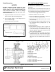
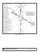
Refer to Figure 14.
1. Remove top cover (22) from gearbox and pour out
gear oil.
2. Remove oil cap (20) (to be replaced).
3. Remove snap ring (10) and shim (13) from input
shaft (3).
4. Support gearbox in hand press and push on input
shaft (3) to remove bearing (7).
5. Remove six cap screws (23) and top cover (22)
from housing. Remove gear (1) from inside
housing.
6. Remove oil seal (19) from front of housing (to be
replaced).
7. Remove snap ring (10) and shim (13) from front of
housing (2).
8. Remove input bearing (7) by using a punch and
hammer from outside of housing.
9. Support housing in vise in a horizontal position.
10. The castle nut (15), cotter pin (25), and hub are
already removed with the stump jumper/crossbar.
Remove the protective seal (8), and oil seal (18).
11. Remove cotter pin (9), castle nut (14), and shim
(17) from output shaft (4).
12. Remove output shaft (4) by using a punch and
hammer and tap on top to drive down. Remove
gear (5) and shim (16) from inside housing.
13. Remove bottom bearing (21) by using a punch and
hammer from the top, outside the housing.
14. Support housing upside down (top cover surface)
and remove bearing (6) by using a punch and
hammer from the bottom side of the housing.
15. Inspect gears for broken teeth and wear. Some
wear is normal and will show on loaded side.
Forged gear surfaces are rough when new. Check
that wear pattern is smooth.
16. Inspect vertical and horizontal shafts for grooves,
nicks, or bumps in the areas where the seals seat.
Resurface any damage with emery cloth.
17. Inspect housing and caps for cracks or other
damage.
Assembly
Refer to Figure 14.
1. Clean housing, paying specific attention to areas
where gaskets will be installed.
2. Wash housing and all components thoroughly.
Select a clean area for gearbox assembly. Replace
all seals, bearings, and gaskets. All parts must be
clean and lightly oiled before reassembling.
3. Insert both output bearings (6 & 21) in the housing,
using a round tube of the correct diameter and a
hand press.
4. Slide output shaft (4) through both bearings (6 &
21) until it rests against top bearing (6).
5. Slide shim (16) over output shaft (4).
6. Press gear (5) onto output shaft (4) and secure
with shim (17), castle nut (14), and cotter pin (9).
7. Apply grease to lower seal lips (18) and press seal
(18) over output shaft (4), using a tube of the
correct diameter. Be sure not to damage the seal
lip.
8. Press in housing so that seal is recessed. Press
protective seal (8) until seated flush with housing.
Verify that the seal (8) is seated correctly.
9. Press bearing (7) into the housing, using a round
tube of the correct diameter and a hand press.
Secure with shim (13) and snap ring (10).
10. Secure snap ring (11) on input shaft (3) if not
already secure.
11. Place gear (1) through top of housing and align
gear (1) and gear (5) so that gear teeth are a
match.
12. While holding gear (1) in place, slide input shaft (3)
through gear (1) and bearing (7). Align splines on
shaft (3) and gear (1).
13. Slide shim (12) over input shaft (3) and press
bearing (7) onto input shaft (3), using a round tube
of the correct diameter and a hand press.
14. Slide shim (13) over input shaft (3) and secure with
snap ring (10).
15. Check input shaft end float by moving the input
shaft (3) by hand. If end float is higher than 0.012",
insert shim between input shaft (3) and rear
bearing (7). Repeat until end float is less than
0.012". Check rotational torque by hand. The
torque should be less than 2.2 lbs-inch.