
Company Brush Cutter User Manual


38 Assembly
MAN0763 (10/10/2008)
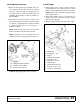
Figure 29. Wing Cylinder & Wing Transport Lock Installation
Install Wing Wheel Yoke
1. Attach wing wheel yoke (6) to the wing using pivot
pins (31). Make sure pin flange is on the underside
of the deck. See Figure 30.
2. Secure pivot pins to deck using carriage bolts (67)
and flange lock nuts (53). Carriage bolts are on the
outside, lock nuts on the underside.
3. Insert wheel hub (17) into wing wheel yoke arm (6)
and align holes.
4. Secure into position using cap screw (30) and
flanged lock nut (53).
5. Attach wheel to hub using five lug nuts. Install the
chamfered side of the lug nut toward the inside for
steel rim for pneumatic tires and rims. Tighten to 75
lbs-ft. Set tire pressure to a maximum of 40 psi.
NOTE: Install the flat side of the nut toward the
inside for solid tires and aircraft tires (shown).
6. Install optional dual wheel and hub to inside of
wheel yoke arm.
Figure 30. Wing Wheel and Hub Installation - Right
5. Hydraulic cylinder
18. 1" x 4.58" Clevis pin
19. 1" x 5.08" Clevis pin
20. Wing transport lock
23. 1/4 NPT x 1/4 NPT Elbow, restricted
24. 1/2 NPT x 1/4 NPT Reducer bushing
25. 1/4 NPT x 1/4 NPT x 264" Hose
29. 1 x 8.41 Headless pin
33. 1" Flat washer
40. Lynch pin, chain & cotter asy
63. 1/4 x 1-1/2 Cotter pin
6. Wing wheel yoke arm, right
17. Wheel and hub
30. 1/2 NC x 3 HHCS GR5
31. Pivot pin, 1-1/4
53. 1/2 NC Flanged lock nut
67. 1/2 NC x 1-1/2 Carriage bolt