
Company Brush Cutter User Manual


26 Dealer Service
MAN0764 (11/5/2008)
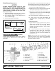
Horizontal Shaft Seal Replacement
1. Disconnect and remove the driveline from the
gearbox.
2. Remove dipstick breather assembly (30), Figure
11, and siphon gear lube from housing through this
opening.
3. Remove input oil seal (6). Replace with new one.
4. Fill gearbox with SAE 80W or 90W gear lube to the
center of the horizontal shaft or until oil is between
lowest ring and end of dipstick.
WING & CENTER GEARBOX REPAIR
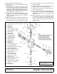
Gearbox Cap Leak Repair (Figure 11)
1. Disconnect and remove the driveline from gearbox.
2. Remove dipstick breather assembly (30) and
siphon gear lube from housing through this
opening.
3. Remove cap where leak is occurring (4, 21 or 26).
4. Clean mating surfaces with a gasket remover.
5. Replace gaskets (7, 8, 22, 23, 31) as required to
meet the following specifications:
● End float should be less than 0.012".
● Rotational torque should be less than 2.2 lbs-
inch.
● Gear backlash should be between 0.006" and
0.016".
6. Install cap (4, 21 or 26) using a gasket sealant.
7. Install cap screws (3 or 25) and torque to 29 lbs-ft.
8. Fill gearbox with SAE 80W or 90W gear lube to the
center of the horizontal shaft or until oil is between
lowest ring and end of dipstick.
Gearbox Removal
NOTE: Gearbox is heavy: do not attempt to move with-
out mechanical assistance.
1. Disconnect and remove the driveline from the
gearbox that is to be removed.
2. Remove cotter pin and nut from vertical shaft and
remove crossbar (see page 30).
3. Remove the eight bolts that attach gearbox to
cutter and remove gearbox.
Gearbox Disassembly (Figure 11)
1. Remove six cap screws (25) and cover (26) from
gearbox and pour out gear oil.
2. Remove caps (21 & 4).
3. Support gearbox in a hand press and push on the
gear end of input shaft (5) to remove bearing (20).
4. Remove gear (32) from inside housing.
5. Remove bearing (20) by using a punch and
hammer from outside of housing.
6. Support housing in vise in a horizontal position.
7. The castle nut (14), cotter pin (13), and hub were
already removed with the stump jumper/crossbar.
Remove the ring (33), and oil seal (15).
8. Remove cotter pin (19) and nut (18) from output
shaft (16).
9. Remove output shaft (16) by using a punch and
hammer and tap on top to drive down. Remove
gear (17) and shims (9, 10, 11) from inside
housing.
10. Remove bottom bearing (12) by using a punch and
hammer from the top, outside the housing.
11. Support housing upside down (top cover surface)
and remove bearing (20) by using a punch and
hammer from the bottom side of the housing.
12. Inspect gears for broken teeth and wear. Some
wear is normal and will show on loaded side.
Forged gear surfaces are rough when new. Check
that the wear pattern is smooth.
13. Inspect vertical and horizontal shafts for grooves,
nicks, or bumps in the areas where the seals seat.
Resurface any damage with emery cloth.
14. Inspect housing and caps for cracks or other
damage.
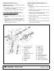
Gearbox Assembly (Figure 11)
1. Clean housing, paying specific attention to areas
where gaskets will be installed.
2. Wash housing and all components thoroughly.
Select a clean area for gearbox assembly. Replace
all seals, bearings, and gaskets. All parts must be
clean and lightly oiled before reassembling.
3. Insert both output bearings (12, 20) in the housing,
using a round tube of the correct diameter and a
hand press.
4. Slide output shaft (16) from the bottom through
both bearings (12, 20) until it rests against bottom
bearing (12).
5. Slide shims (9, 10, 11) over output shaft (16). Use
the same thickness of shims that were removed as
a starting point.
6. Place gear (17) onto output shaft (16) and secure
with nut (18), and cotter pin (19). The output shaft
must have zero endplay and a rotation torque of
20/30 LBS-IN without the lower seal. Tighten nut
(18) as required.
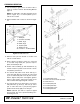
7. Press bearing cup (20) into end of the housing
closest to the gear, using a round tube of the
correct diameter and a hand press. Install cap (4 or
21) and gaskets (7, 8 or 22, 23).
8. Place gear (32) and spacers (29, 24) through top of
housing and align gear (32) and shaft (5) so that
gear spline matches the shaft spline.
9. While holding gear (32) in place, slide input shaft
(5) through gear (32) and press onto bearing cone
(20).
(Rev. 8/20/2009)