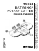
ROTARY CUTTER BW240HD, BW240HDQ OPERATOR'S MANUAL (Rev.
TO THE DEALER: Assembly and proper installation of this product is the responsibility of the Woods® dealer. Read manual instructions and safety rules. Make sure all items on the Dealer’s Pre-Delivery and Delivery Check Lists in the Operator’s Manual are completed before releasing equipment to the owner. The dealer must complete the online Product Registration form at the Woods Dealer Website which certifies that all Dealer Check List items have been completed.
TABLE OF CONTENTS INTRODUCTION . . . . . . . . . . . . . . . . . . . . . . . . . . . . . . . . . . . . . . . . . . . . . . 2 SPECIFICATIONS . . . . . . . . . . . . . . . . . . . . . . . . . . . . . . . . . . . . . . . . . . . . . 4 GENERAL INFORMATION . . . . . . . . . . . . . . . . . . . . . . . . . . . . . . . . . . . . . . 4 SAFETY VIDEO ORDER FORM . . . . . . . . . . . . . . . . . . . . . . . . . . . . . . . . . . 5 SAFETY RULES . . . . . . . . . . . . . . . . . . . . . . . . . . . . . . . . . . . . . .
SPECIFICATIONS BW240HD / BW240HDQ Cutting Height (Varies with tire selection) . . . . . . . . . . . . . . . . . . . . . . . . . . . . . . . . . . . . . . . . . . . . . 2" - 15" Cutting Width . . . . . . . . . . . . . . . . . . . . . . . . . . . . . . . . . . . . . . . . . . . . . . . . . . . . . . . . . . . . . . . . . 240" (20’) Overall Width . . . . . . . . . . . . . . . . . . . . . . . . . . . . . . . . . . . . . . . . . . . . . . . . . . . . . . . . . . . . . . . . . . . . . .249" Transport Width . . .
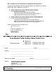
Safety Video Order Form BE SAFE! BE ALERT! BE ALIVE! BE TRAINED Before Operating Mowers! Safety Training Does Make a Difference. ASSOCIATION OF EQUIPMENT MANUFACTURERS Free Mower Safety Video Fill out and return the order form and we will send you a FREE VHS or DVD video outlining Industrial and Agricultural Mower Safety Practices.
Also, available from the Association of Equipment Manufacturers: A large variety of training materials (ideal for groups) are available for a nominal charge from AEM.
SAFETY RULES ATTENTION! BECOME ALERT! YOUR SAFETY IS INVOLVED! Safety is a primary concern in the design and manufacture of our products. Unfortunately, our efforts to provide safe equipment can be wiped out by an operator’s single careless act. In addition to the design and configuration of equipment, hazard control and accident prevention are dependent upon the awareness, concern, judgement, and proper training of personnel involved in the operation, transport, maintenance, and storage of equipment.
SAFETY RULES ATTENTION! BECOME ALERT! YOUR SAFETY IS INVOLVED! (Safety Rules continued from previous page) Make sure driveline guard tether chains are attached to the tractor and equipment as shown in the pamphlet that accompanies the driveline. Replace if damaged or broken. Check that driveline guards rotate freely on driveline before putting equipment into service. Connect PTO driveline directly to power unit PTO shaft. Never use adapter sleeves or adapter shafts.
SAFETY RULES ATTENTION! BECOME ALERT! YOUR SAFETY IS INVOLVED! Full chain or rubber shielding must be installed when operating in populated areas or other areas where thrown objects could injure people or damage property. • If this machine is not equipped with full chain or rubber shielding, operation must be stopped when anyone comes within 300 feet (92 m). • This shielding is designed to reduce the risk of thrown objects.
SAFETY RULES ATTENTION! BECOME ALERT! YOUR SAFETY IS INVOLVED! (Safety Rules continued from previous page) Never go underneath equipment (lowered to the ground or raised) unless it is properly blocked and secured. Never place any part of the body underneath equipment or between moveable parts even when the engine has been turned off.
SAFETY & INSTRUCTIONAL DECALS ATTENTION! BECOME ALERT! YOUR SAFETY IS INVOLVED! Replace Immediately If Damaged! MODEL NO. SERIAL NO. Woods Equipment Company Oregon, Illinois, U.S.A. 1 - SERIAL NUMBER PLATE PN 1006348 - Located on Wheel Rims EXPLOSION HAZARD FAILURE TO DO SO COULD RESULT IN SERIOUS INJURY OR DEATH. MAX. SPEED: 20 MPH, MAX. WEIGHT: 4000 LBS., MAX. AIR PRESSURE: 40 PSI. BE CAREFUL! Use a clean, damp cloth to clean safety decals.
SAFETY & INSTRUCTIONAL DECALS ATTENTION! BECOME ALERT! YOUR SAFETY IS INVOLVED! Replace Immediately If Damaged! 7 - PN 15503 WARNING DO NOT EXCEED PTO SPEED OF DANGER 5 - PN 15922 1000 RPM PTO speeds higher than 1000 RPM can cause equipment failure and personal injury. 15922-C OR WARNING ROTATING BLADES AND THROWN OBJECTS Do not put hands or feet under or into mower when engine is running. DO NOT EXCEED PTO SPEED OF Before mowing, clear area of objects that may be 540 RPM thrown by blade.
SAFETY & INSTRUCTIONAL DECALS ATTENTION! BECOME ALERT! YOUR SAFETY IS INVOLVED! Replace Immediately If Damaged! 12 - PN 1004991 WARNING TRANSPORT LOCK AND CYLINDER REQUIREMENTS RAISED CUTTER CAN DROP AND CRUSH SINGLE-ACTING FULL EXTENSION Cutte ers must be equipped with transport lock. 28-1/4" stands.
OPERATION The designed and tested safety of this machine depends on it being operated within the limitations as explained in this manual. Be familiar with and follow all safety rules in the manual, on the cutter and on the tractor. sturdy, rough-soled work shoes and protective equipment for eyes, hair, hands, hearing, and head; and respirator or filter mask where appropriate. The safe operation of this cutter is the responsibility of the operator, who must be properly trained.
Hydraulic Connection 1. Inspect hydraulic hoses to ensure they are in good condition. 2. Clean the fittings before connecting them to the tractor hydraulic ports. 3. Route the hose through the hose holder at the hitch and be sure the hose can slide freely in the holder. Do not allow hose slack to drag on the ground or become caught on tractor protrusions. 4. Attach the hydraulic hose to the tractor. 5.
cutter drive system. Increase throttle to recommended PTO operating RPM. Be sure operator is familiar with all controls and can stop tractor and cutter quickly in an emergency. The operator should give complete, undivided attention to operating tractor and cutter. CUTTER OPERATION When beginning operation of the cutter, make sure that all persons are in a safe location. Power for operating the cutter is supplied by the tractor PTO. Operate PTO at 540 (1000 RPM for "Q" models).
Use extreme care and reduce ground speed on slopes and rough terrain. Always attach safety chain to tractor drawbar when transporting unit. Watch for hidden hazards on the terrain during operation. Never exceed 20 mph (32.2 km/h) during transport. Never allow riders on power unit or attachment. CAUTION Stop power unit and equipment immediately upon striking an obstruction. Turn off engine, remove key, inspect, and repair any damage before resuming operation.
PRE-OPERATION CHECK LIST Center Section Lock-Up (OWNER'S RESPONSIBILITY) ___ Review and follow all safety rules and safety decal instructions on page 7 through page 13. ___ Check that all safety decals are installed and in good condition. Replace if damaged. ___ Check that equipment is properly and securely attached to tractor. DP8A ___ Make sure driveline spring-activated locking pin or collar slides freely and is seated firmly in tractor PTO spline groove. 1.
OWNER SERVICE The information in this section is written for operators who possess basic mechanical skills. If you need help, your dealer has trained service technicians available. For your protection, read and follow the safety information in this manual. WARNING Keep all persons away from operator control area while performing adjustments, service, or maintenance.
1. 2. 3. 4. Driveline U-joint Telescoping shaft Carrier bearing block CV body assembly (10 pumps minimum) 5. Driveline shield 6. Splined yoke 7. Gearbox (above lower line on dipstick) 8. Tongue pivot 9. Wheel yoke pivot 10. Gearbox (bottom of side hole) 11. Tailwheel spindle 12. Turnbuckle 10 Hours 10 Hours 40 Hours 10 hours 10 Hours 10 Hours Daily 40 Hours 40 Hours Daily 20 Hours 40 Hours Figure 4.
Seasonal Lubrication lock clip (12, keyhole plate (11), and shims (9 & 10). Carefully drive blade pin (7) out of crossbar. In addition to the daily recommended lubrication, a more extensive application is recommended seasonally. 1. Fill CV double yokes with 20 pumps of grease with the joints in a straight line. 2. Articulate CV body to maximum angle several times to ensure full coverage of joints. 3. Place joints in the straight position and add 10 additional pumps of grease to both joints. 4.
Blade Sharpening SLIP CLUTCH ADJUSTMENT (Figure 7) NOTICE ■ When sharpening blades, grind the same amount on each blade to maintain balance. Replace blades in pairs. Unbalanced blades will cause excessive vibration, which can damage gearbox bearings. Vibration may also cause structural cracks to cutter. 1. Sharpen both blades at the same time to maintain balance. Follow original sharpening pattern. 2. Do not sharpen blade to a razor edge—leave at least a 1/16" blunt edge. 3.
SHIELDING REPAIR DANGER Check wheels for low pressure, cuts, bubbles, damaged rims, or missing lug bolts and nuts. Never remove split rim assembly hardware (A) with the tire inflated. Full chain or rubber shielding must be installed when operating in populated areas or other areas where thrown objects could injure people or damage property. • If this machine is not equipped with full chain or rubber shielding, operation must be stopped when anyone comes within 300 feet (92 m).
TROUBLESHOOTING PROBLEM Does not cut POSSIBLE CAUSE SOLUTION Dull blades Sharpen blades. Worn or broken blades Replace blades. (Replace in pairs only.) Incorrect PTO speed Set at rated PTO speed. Ground speed too fast Reduce ground speed. Drive not functioning (blades do not turn when PTO is running) Check drive shaft connection. Check gearbox. Gearbox malfunction Repair gearbox. Excessive clutch slippage Adjust clutch.
DEALER SERVICE The information in this section is written for dealer service personnel. The repair described here requires special skills and tools. If your shop is not properly equipped or your mechanics are not properly trained in this type of repair, you may be time and money ahead to replace complete assemblies. WARNING ■ Before Seal Replacement (Figure 9) Recommended sealant for gearbox repair is Permatex® Aviation 3D Form-A-Gasket or equivalent.
1. Disconnect and remove the rear driveline from the gearbox. 5. Remove six cap screws (23) and top cover (22) from housing. Remove gear (1) from inside housing. 2. Remove vent plug (24) and siphon gear lube from housing through this opening. 6. Remove oil seal (19) from front of housing (to be replaced). 3. Remove crossbar (see page 30). 7. Remove snap ring (10) and shim (13) from front of housing (2). Vertical Shaft Seal Replacement (Figure 10) 4.
correct diameter. Be sure not to damage the seal lip. 0.012". Check rotational torque by hand. The torque should be less than 2.2 lbs-inch. 8. Press in housing so that seal is recessed. Press protective seal (8) until seated flush with housing. Verify that the seal (8) is seated correctly. 16. Check that the gear backlash is between 0.006" and 0.016". You should not have to adjust the backlash. 9. Press bearing (7) into the housing, using a round tube of the correct diameter and a hand press.
SPLITTER GEARBOX REPAIR (Figure 11) 1. Clean housing, pay specific attention to areas where gaskets are installed. Removal from Cutter 1. Disconnect gearbox. and remove Assembly all drivelines from 2. Remove the four cap screw and lock washers that secure gearbox to cutter, and remove gearbox. NOTE: Gearbox is heavy: do not attempt to move it without mechanical assistance. Disassembly Center Shaft 2. Wash housing and all components thoroughly. 3. Select a clean work area to assemble gearbox. 4.
Gearbox Inspection 4. Install breather (24) in top cover. 1. Check gearbox for leaks by: plugging all holes except one, applying 4 psi of compressed air, and immersing gearbox in water. Verify gearbox does not leak. NOTE: Excessive air pressure will damage seals. 2. Remove gearbox from water and dry off. 3. Remove upper plug on right side of housing. Add SAE 80W or 90W EP oil until it runs out side level hole. Replace plug.
CROSSBAR REMOVAL 1. It is necessary to gain access to bottom side of cutter for crossbar removal. See Blocking Method page 19. NOTE: You will need to use either the puller screw (Item 6, Figure 13) or a small hydraulic jack to remove the crossbar. 2. Remove blades from crossbar as shown in Figure 12. 7. 8. 9. 10. 11. 12. 50. Blade pin Crossbar assembly Shim, 18 ga Shim, 20 ga Keyhole plate Blade lock clip 1/2 NC x 1-1/4 HHCS GR5 Figure 12. Blade Removal 3.
CROSSBAR INSTALLATION 1. Using emery cloth (220 or finer), remove surface rust, Loctite® and foreign material from hub, splined gearbox vertical shaft, and crossbar assembly. 2. Slide crossbar assembly (8) onto splined shaft. Install nut (69) and align a slot with hole in splined shaft. Torque nut to 800 lbs-ft. 3. Install cotter pin (70) through slot in nut and bend ends over. Figure 16 2. With snap rings removed, support drive in vise, hold yoke in hand and tap on yoke to drive cup up out of yoke.
4. Place universal cross in vise as shown in Figure 19 and tap on yoke to remove cup. Repeat Step 3 for final removal. Drive remaining cup out with a drift and hammer. SERVICE TIRES SAFELY Used Aircraft Tires (Figure 20) WARNING Do not attempt to mount a tire unless you have the proper equipment and experience to perform the job. Always maintain the correct tire pressure. Do not inflate tires above the recommended pressure. Never weld or heat a wheel and tire assembly.
ASSEMBLY INSTRUCTIONS DEALER SET-UP INSTRUCTIONS Assembly of this cutter is the responsibility of the WOODS dealer. It should be delivered to the owner completely assembled, lubricated and adjusted for normal cutting conditions. The cutter is shipped partially assembled. Assembly will be easier if components are aligned and loosely assembled before tightening hardware. Recommended torque values for hardware are located on page 72. 3.
3. Tighten nuts until there is approximately 1 inches of thread exposed past the nuts. Further adjustment will be needed once cutter is attached to tractor drawbar. See Cutting Height Adjustment, page 15. Install Height Adjustment Cylinder Refer to Figure 23. 1. Attach base end of cylinder (3) to the cylinder lugs on the rear of the deck using clevis pin (18) and two cotter pins (63). 2. Extend cylinder rod and place transport lock bracket (5) over cylinder rod clevis. 3.
Install Spring Wheel Arms 1. Slide right spring wheel arm assembly (14) over center wheel yoke tube and secure into position using four cap screw (28) and flanged lock nut (37). Repeat step to install left spring wheel arm assembly. Keep spacing as wide as possible for greater stability. 2. Attach wheels to hubs using five lug nuts. Install the chamfered side of the lug nut toward the inside for steel rim for pneumatic tires and rims. Tighten to 75 lbs-ft.
Install 3-Joint Drive (540 RPM Only) Before installing cutter input driveline to gearbox, check the tag wired to the driveline and the tag wired to the input shaft of gearbox. Ensure the tag rpm speeds match the rpm speed decal on front of cutter. After confirming all speeds match, remove and discard tags and then complete driveline assembly. 1. Attach H-frame (24) to tongue with cap screw (44), sleeves (46), cup washers (45), and nut (47). 2. Coat splined end of gearbox input shaft with grease. 3.
Install CV Drive (Optional) 4. Repeat procedure of opposite wing. Before installing cutter input driveline to gearbox, check the tag wired to the driveline and the tag wired to the input shaft of gearbox. Ensure the tag rpm speeds match the rpm speed decal on front of cutter. After confirming all speeds match, remove and discard tags and then complete driveline assembly. 1. Align hole in drive yoke with groove on gearbox input shaft and slide rear half of drive (23) onto shaft. 2.
5. 18. 19. 20. 23. 24. 25. 29. 33. 40. 63. Hydraulic cylinder 1" x 4.58" Clevis pin 1" x 5.08" Clevis pin Wing transport lock 1/4 NPT x 1/4 NPT Elbow, restricted 1/2 NPT x 1/4 NPT Reducer bushing 1/4 NPT x 1/4 NPT x 264" Hose 1 x 8.41 Headless pin 1" Flat washer Lynch pin, chain & cotter asy 1/4 x 1-1/2 Cotter pin Figure 29. Wing Cylinder & Wing Transport Lock Installation Install Wing Wheel Yoke 4. Secure into position using cap screw (30) and flanged lock nut (53). 1.
Install Wing Wheel Yoke Adjustment Link CAUTION Use a suitable lifting device of sufficient capacity. Use adequate personnel to handle heavy components. 1. With a lifting device raise right wing and lock in the up position using the wing lock-up bar. Leave lifting device attached for added support. 2. Attach adjustable link (turnbuckle, 22) to right side of center wheel yoke arm and secure with cap screw (32) and lock nut (26). Install Wing Driveline 1.
OPTIONAL EQUIPMENT Install Tandem Wheel Assembly (Wing) Install Tandem Wheel Assembly (Center) 1. Slide spring wheel arm assembly (1) over right side of center wheel yoke tube and secure into position using four cap screw (22) and flanged lock nut (23). Repeat step to install spring wheel arm assembly on left side of center wheel yoke tube. 2. Place tandem wheel bracket (16) around lower lower spring arm (13) and insert flange pin (17).
INSTALL CHAIN OR BELT SHIELDING DANGER Full chain shielding must be installed when operating in populated areas or other areas where thrown objects could injure people or damage property. • If this machine is not equipped with full chain shielding, operation must be stopped when anyone comes within 300 feet (92 m). • This shielding is designed to reduce the risk of thrown objects. The mower deck and protective devices cannot prevent all objects from escaping the blade enclosure in every mowing condition.
4-Link 6-Link 1. Front wing chain plate, inner 2. Front wing chain plate, center 3. Front wing chain plate, outer 4. Rear wing chain plate 12. 5/16 Chain - 6-link 13. 5/16 Chain - 4-link 14. 15. 16. 17. 1/2 NC x 1-1/2 Carriage bolt 1/2 NC Flange lock nut 3/8 NC x Carriage bolt 3/8 NC Flange lock nut Figure 35. Chain Shielding Installation - Right Wing Shown 1. 2. 3. 4. 5. 6. 14. 15. Front center belt shield plate Front right belt shield plate Front left belt shield plate Bent link, .25 x 1.61 x 12.
1. 2. 3. 4. Front right wing belt shield plate, outer Front wing belt shield plate, inner Front wing belt shield plate, center Bent link, .25 x 1.61 x 23.50 5. 6. 7. 8. 9. 10. 11. 12. 13. 14. 15. Rear right wing belt shield plate, inner Link .25 x 1.00 x 27.00 Rubber belt, .25 x 8.50 x 27.25 Rubber belt, .25 x 8.50 x 43.50 Rubber belt, .25 x 8.50x 36.05 Rubber belt, .25 x 8.88 x 54.50 Rubber belt, .25 x 3.64 x 28.
DEALER CHECK LISTS PRE-DELIVERY CHECK LIST (DEALER’S RESPONSIBILITY) ___ Show customer how to determine the turning limits of the CV PTO driveline. Inspect the equipment thoroughly after assembly to ensure it is set up properly before delivering it to the customer. ___ Show customer the safe, proper procedures to be used when mounting, dismounting, and storing equipment. The following check lists are a reminder of points to inspect.
PARTS INDEX BATWING® Rotary Cutter BW240HD, BW240HDQ MAIN FRAME ASSEMBLY (FRONT SECTION) ...................................................... 46-47 (REAR SECTION) ......................................................... 48-49 WING ASSEMBLY ........................................................................................................ 50-51 GEARBOX ASSEMBLY WING & CENTER ......................................................... 52-53 SPLITTER ..................................................
MAIN FRAME ASSEMBLY (FRONT SECTION) 46 Parts (Rev.
MAIN FRAME ASSEMBLY (FRONT SECTION) REF 1 2 PART QTY DESCRIPTION 8825KT 1 Blade kit, CCW ----- 1 Gearbox (see page 52) REF PART QTY DESCRIPTION 41 302207 42 300451 * 5/8 NC x 1-1/4 HHCS GR5 3/4 NC Flange lock nut 3 1027297 1 Driveline complete, 1340, 1.75-20 12.6 43 57817 5/8 SAE Hardened flat washer 4 1027125 2 Attitude rod 44 23638 5/8 NC x 7 HHCS GR5 5 1027035 2 Front skid 45 10635 5/8 x 1-3/4 x 14 GA Cup washer 46 1791 6239 * 5/8 NC Hex lock nut 6 19407 1 Safety chain .
MAIN FRAME ASSEMBLY (REAR SECTION) 48 Parts MAN0763 (10/10/2008)
MAIN FRAME ASSEMBLY (REAR SECTION) REF PART QTY DESCRIPTION REF PART QTY DESCRIPTION 1 1027070 1 Center wheel yoke 24 11893 1 1/2 x 1/4 Pipe reducer bushing 2 57050 1 Access hole cover 25 3 10475 1 Hydraulic cylinder 3-1/2 (see page 67) 26 34279 * 1 NC Lock nut 11920 1 x 1-7/8 x 1/4 Washer 3/4 NC x 6 HHCS GR5 1024122 1 NC x 13 HHCS GR5 4 1027125 2 Attitude rod 27 5 1004814 1 Transport lock-up 28 2377 3132 * 1 NC Hex nut 6 24098 1 1-1/4 Cylinder stroke control kit (optional) 2
WING ASSEMBLY Right Wing Shown 50 Parts MAN0763 (10/10/2008)
WING ASSEMBLY REF PART QTY DESCRIPTION REF PART QTY DESCRIPTION 1 8825KT 1 Blade kit, CCW (Right wing) - or - 26 34279 * 1 NC Lock nut 1 8820KT 1 Blade kit, CW (Left wing) 27 11920 1 x 1-7/8 x 1/4 Washer 1 NC x 9 HHCS GR5 2 ----- 1 Gearbox (see page 52) 28 15087 3 1027120 1 Clutch shield with hinge 29 52329 1 1 x 8.41 Headless pin 4 1027296 1 Driveline complete 2400, 63.4 x 83.
WING & CENTER GEARBOX ASSEMBLY 52 Parts MAN0763 (10/10/2008)
WING & CENTER GEARBOX ASSEMBLY 540 RPM Left Wing 1000 RPM Right Wing Left Wing Right Wing REF QTY A 1 1024795 58808 1029848 1024795 58809 1029848 Complete gearbox 1 1 1025617 57446 1025617 1025617 57447 1025617 Gear crown 2 1 NS NS NS NS NS 3 1 57450 57450 57450 57450 57450 57450 Input shaft 4 1 57454 57454 57454 57454 57454 57454 Output shaft 5 1 1025617 57447 1025617 1025617 57446 1025617 Gear pinion 6 2 39263 39263 39263 39263 39263 39263 Beari
SPLITTER GEARBOX ASSEMBLY REF 1 2 3 4 5 6 7 8 9 10 11 12 13 14 15 16 17 18 19 20 21 22 23 24 PART PART 540 RPM 1000 RPM 1029698 1029699 21542 21542 307201 307201 1019613 1019613 1019575 1019575 1019589 1019589 1019587 1019587 1019592 1019592 1019593 1019593 1019594 1019594 1019612 1019612 1019590 1019590 1019576 1019576 1019603 1019603 1019609 1019609 1019608 1019608 1019610 1019610 1027170 1027184 1027184 1027170 1019605 1019605 ------------1009081 1009081 1019601 1019601 1019600 1019600 QTY 24 24 1 1
CENTER DECK DRIVE ASSEMBLY REF PART QTY DESCRIPTION REF PART QTY DESCRIPTION A 1027297 1 Complete center drive assembly 9 57434 1 Thrust plate 1 1004961 1 Yoke, 1-3/4, 20 spline 10 57439 1 Belleville spring plate 2 110 2 Cross & bearing kit 11 57259 6 M10 x 1.5P x 55 mm Cap screw 8.8 3 40576 1 Inboard yoke 12 57260 6 M10 x 1.5P Hex lock nut 4 1005521 1 Grease fitting 13 57261 2 M12 x 1.
FRONT 3-JOINT DRIVE ASSEMBLY (EQUAL ANGLE) 540 ONLY REF PART QTY 1 DESCRIPTION A 57282 Complete 540 RPM (6 spline) 1 40563 1 Yoke 1-3/8 - 6 spline (540 RPM) 2 40566 2 Cross & bearing 3 40751 2 Inboard yoke 4 40753 1 Outer profile 5 40765 2 Spring pin 10 x 90 6 57299 1 Yoke 1-1/2 - 23 spline I.C.
REAR 3-JOINT DRIVE ASSEMBLY (EQUAL ANGLE) REF PART QTY DESCRIPTION REF PART QTY DESCRIPTION A 1004932 1 Complete rear drive assembly 9 40777 2 Anti-rotation chain 1 1004957 1 Yoke, 1-3/4, 20 spline 10 40767 1 Support bearing 2 40566 1 Cross and bearing 11 18864 1 Decal, danger rotating driveline 3 1003471 1 Inboard yoke 12 33347 1 Decal, danger guard missing 4 1004958 1 Inner profile 13 1004960 1 Inner guard half 5 40765 1 Spring pin 10 x 90 14 1004959
540 RPM FRONT CV DRIVE REF PART QTY A 1 2 3 4 5 1021103 19851 58774 58759 58760 1021313 1 1 1 2 1 1 6 7 1009065 18864 † 2 1 8 1021314 1 DESCRIPTION Complete CV drive (540 RPM) Slide lock repair kit Yoke QD CV 1.375 - 6 (540 RPM) CV U-Joint repair kit Cat 6 55E CV Body with fitting Yoke and shaft CV splined 25.
1000 RPM FRONT CV DRIVE 1000 RPM 1-3/8 21-Splined REF PART A 1021104 1 1 19851 1 2 58770 1 Yoke QD CV 1.375 - 21 3 58759 2 CV U-Joint repair kit, cat 6 55E 4 58760 1 5 1021317 1 6 1009065 7 18864 † QTY DESCRIPTION 1000 RPM 1-3/4 20-Splined REF PART QTY Complete CV drive assembly A 1021105 1 Complete CV drive assembly Slide lock repair kit 1 19837 1 Slide lock repair kit 2 58758 1 Yoke QD CV 1.
WING DRIVE ASSEMBLY REF PART QTY DESCRIPTION 1 1027296 2 1019111 1 Yoke 1-3/4 20 special 3 4 5 Complete wing drive assembly 38352 2 Cross and bearing kit 2400 90317352 1 Inboard yoke S4 40764 2 Spring pin 10 x 80 REF PART QTY DESCRIPTION 15 40779 1 Grease fitting 16 44677 1 Inboard yoke S5 17 1019114 1 Clutch (includes 18 thru 24, 27,28) 18 1027217 1 Flange yoke 19 57432 2 Friction disc 6 1019112 1 Inner profile S4L 20 57440 1 Hub 1-3/4 20 7 1019115 1 Outer shield 21 57262 2
5-BOLT WHEEL & TIRE ASSEMBLY REF PART QTY DESCRIPTION REF PART QTY DESCRIPTION 1 1017050 1 Heavy hub assembly (includes items 1 through 15) 16 1028820F 1 24 x 7.25 x 12 Aircraft tire, rim & hardware, foam filled - 5 bolt 2 1017034 1 Heavy wheel hub with cups (includes items 6,7,14) 16 1017030 1 29 x 9 x 15 Aircraft tire, rim & hardware - 5 bolt 3 1017033 1 Axle 17 1028821 1 4 1017027 1 Seal 12.
RUBBER SHIELDING - CENTER SECTION (STANDARD) REF PART QTY DESCRIPTION 1 1027164 1 Front center belt shield plate 2 1027166 1 Front right belt shield plate 3 1027167 1 Front left belt shield plate 4 1027176 4 Bent link .25 x 1.61 x 12.00 5 1027284 2 Rubber shield .25 x 8.50 x 44.74 6 1027289 2 Rubber shield .25 x 8.88 x 32.50 14 6697 * 3/8 NC x 1 Carriage bolt GR5 15 14350 * 3/8 NC Flanged lock nut * Standard hardware, obtain locally 62 Parts (Rev.
RUBBER SHIELDING - WING (STANDARD) REF PART QTY DESCRIPTION REF PART QTY DESCRIPTION 1 1027168 1 Front right wing belt shield plate, outer - or - 8 9 1027287 1 Rubber shield .25 x 8.50 x 36.05 1 1027169 1 Front left wing belt shield plate, outer 10 1027288 1 Rubber shield .25 x 8.88 x 54.50 2 1027171 1 Front wing belt shield plate, inner 11 1027290 1 Rubber shield .25 x 3.64 x 28.
CHAIN SHIELDING - CENTER SECTION (OPTIONAL) DOUBLE ROW SINGLE ROW REF PART QTY DESCRIPTION REF PART QTY DESCRIPTION 1 1027131 1 Front center chain plate 1 1029881 1 Front center chain plate 2 1027132 1 Front right chain plate 2 1029882 1 Front right chain plate 3 1027133 1 Front left chain plate 3 1029883 1 Front left chain plate 4 1027141 2 Rear chain plate 4 1029888 2 Rear chain plate 8 1003644 4 Pin, 22 to 24 chains 8 1003644 8 Pin, 22 to 24 chains 9 1003646 1 Pin, 28 to 30
CHAIN SHIELDING - WING (OPTIONAL) DOUBLE ROW SINGLE ROW REF PART QTY DESCRIPTION REF PART QTY DESCRIPTION 1 1027134 1 Front wing chain plate, inner 1 1029885 1 Front wing chain plate, inner 2 1027140 1 Front wing chain plate, center 2 1029884 1 Front wing chain plate, center 3 1027136 1 Front right wing chain plate, outer - or - 3 1029886 1 Front right wing chain plate, outer - or - 3 1027137 1 Front left wing chain plate, outer 3 1029887 1 Front left wing chain plate, outer 4 102
TANDEM AXLE WHEEL YOKE (OPTIONAL) REF PART QTY DESCRIPTION REF PART QTY DESCRIPTION 1 1024109 2 Wheel yoke arm, spring 11 2 1027080 1 Wheel yoke, spring right (for right wing) -or- 12 13 1023170 2 Lower spring arm, tandem 2 1027081 1 Wheel yoke, spring left (for left wing) (not shown) 14 1017149 2 Bar drilled. 1.25 x 8.85 3 1029876 1 Lower spring arm, wing right (for right wing) -or- 16 1023166 4 Tandem 17 1017065 4 Flag pin 1.56 x 11.
HYDRAULIC CYLINDERS 3-1/2 x 8 3-1/2 x 16 REF PART PART QTY 1 2 2A 2B 2C 2D 2E 2F 2G 3 4 5 6 7 8 9 10 11 12 13 10475 23540 † † † † † † † N/S N/S N/S N/S * N/S N/S N/S N/S N/S * 52234 23540 † † † † † † † N/S N/S N/S N/S * N/S N/S N/S N/S N/S * 1 1 1 1 2 2 2 1 1 1 1 4 3 1 2 8 1 1 1 † * N/S MAN0763 (10/10/2008) DESCRIPTION Complete cylinder Seal repair kit (includes items 2A - 2G) Wiper seal Rod seal Rod O-ring Cap seal Cap O-ring Piston seal Piston O-ring Cylinder housing - rod end Piston Jam nut C
HYDRAULIC CYLINDER STROKE CONTROL KIT REF PART QTY DESCRIPTION 1 24098 1 Stroke control set for 1-1/4" cylinder rod (contains items 2 - 5) 2 –––– 2 1-1/2" Segment 3 –––– 1 1-1/4" Segment 4 –––– 1 1" Segment 5 –––– 1 3/4" Segment CROSSBAR PULLER (OPTIONAL) REF PART QTY DESCRIPTION REF PART QTY DESCRIPTION A 8811 1 Crossbar puller, complete 4 24879 1 Crossbar puller pad assembly 1 19914 2 Crossbar puller clevis 5 24876 1 Crossbar puller tube assembly 2 3097 *
WINCH KIT (OPTIONAL) DESCRIPTION Winch Kit Operation REF PART QTY A 1019456 - Winch kit, complete 1 52478 4 Idler bracket 1. Move cutter so wing is on the up slope of a ditch to aid in wing lift with the winch. 2 6696 2 Chain idler casting 2. Unwind cable and remove roller (2). 3 409 2 Clevis pin, 1/2 x 2 4 22411 2 Klik pin, 3/16 x 1 3. Place cable around roller (2) and reinstall using pin (3) and klik pin (4).
BW240HD SHREDDER KIT (OPTIONAL) (THIS KIT DOES NOT FIT BW240) REF PART QTY DESCRIPTION REF PART QTY DESCRIPTION A 1032966 1 BW240HD Shredder kit, complete 8 39127 6 Bushing 1 2 1032967 39002KT 3 2 Crossbar Blade, .5 x 4 x 22.5 CW formed 9 10 39128 7832 * 6 6 Jam nut, 1-1/4 5/8 NC x 1-1/2 HHCS GR5 3 4 39003KT 1017128KT 4 6 Blade, .5 x 4 x 22.5 CCW formed Blade, .5 x 4 x 22.5 flat 11 12 5 6 39089 1014164 3 2 Blade, .38 x 4 x 11.
NOTES MAN0763 (10/10/2008) Parts 71
BOLT TORQUE CHART Always tighten hardware to these values unless a different torque value or tightening procedure is listed for a specific application. Fasteners must always be replaced with the same grade as specified in the manual parts list. Always use the proper tool for tightening hardware: SAE for SAE hardware and Metric for metric hardware. Make sure fastener threads are clean and you start thread engagement properly.
BOLT SIZE CHART NOTE: Chart shows bolt thread sizes and corresponding head (wrench) sizes for standard SAE and metric bolts. SAE Bolt Thread Sizes 5/16 3/8 1/2 IN MM 5/8 3/4 7/8 1 2 3 4 5 6 7 25 50 75 100 125 150 175 Metric Bolt Thread Sizes 8MM 10MM 12MM 14MM 16MM 18MM ABBREVIATIONS AG .............................................................. Agriculture ASABE.................... American Society of Agricultural & Biological Engineers (formerly ASAE) ASAE .......
INDEX A O ADJUSTMENTS Cutting Height 15 Slip Clutch 22 OPERATION Connecting Cutter to Tractor ASSEMBLY Dealer Set-Up Instructions Fill Gearboxes 39 Optional Equipment 40 14 Cutting Height Adjustment 15 CV Driveline Turning Limits 15 Hydraulic Connection 15 Interference Check 15 33 Cutter Operation 16 Mowing Tips 16 Shredding 17 D DEALER CHECK LIST Check Lists Delivery (Dealer’s Responsibility) 44 Pre-Delivery (Dealer’s Responsibility) Pre-Operation Check List (Owner’s Responsibility) Storage 18
WARRANTY All Models Except Mow’n MachineTM Zero-Turn Mowers Please Enter Information Below and Save for Future Reference. Date Purchased: ____________________________ From (Dealer): __________________________________________ Model Number: ____________________________ Serial Number: __________________________________________ Woods Equipment Company (“WOODS”) warrants this product to be free from defect in material and workmanship.
WARRANTY (Replacement Parts For All Models Except Mow’n MachineTM Zero-Turn Mowers and Woods BoundaryTM Utility Vehicles) Woods Equipment Company (“WOODS”) warrants this product to be free from defect in material and workmanship for a period of ninety (90) days from the date of delivery of the product to the original purchaser with the exception of V-belts, which will be free of defect in material and workmanship for a period of 12 months.