(Rev. 3/9/2010) MAN0450 BH70-X, BH80-X Tested. Proven. Unbeatable.
TO THE DEALER: Assembly and proper installation of this product is the responsibility of the Woods® dealer. Read manual instructions and safety rules. Make sure all items on the Dealer’s Pre-Delivery and Delivery Check Lists in the Operator’s Manual are completed before releasing equipment to the owner. The dealer must complete the online Product Registration form at the Woods Dealer Website which certifies that all Dealer Check List items have been completed.
TABLE OF CONTENTS INTRODUCTION . . . . . . . . . . . . . . . . . . . . . . . . . . . . . . . . . . . . . . . . . . . . . . 2 SPECIFICATIONS . . . . . . . . . . . . . . . . . . . . . . . . . . . . . . . . . . . . . . . . . . . . . 4 GENERAL INFORMATION . . . . . . . . . . . . . . . . . . . . . . . . . . . . . . . . . . . . . . 6 SAFETY RULES . . . . . . . . . . . . . . . . . . . . . . . . . . . . . . . . . . . . . . . . . . . . . . 7 SAFETY DECALS . . . . . . . . . . . . . . . . . . . . . . . . . . . . . . .
BH70-X & BH80-X SPECIFICATIONS English Description Transport Height* Metric Illustration BH70-X BH80-X BH70-X BH80-X A 74.75" 82.25" 1899 mm 2090 mm 58.5" 58.5" 1486 mm 1486 mm 15° 15° 15° 15° Stabilizer Spread (Transport)* Angle of Departure** Digging Depth, Maximum* F 86.25" 98." 2191 mm 2489 mm Digging Depth, 2 ft. Flat Bottom* G 84.5" 96.5" 2146 mm 2451 mm Digging Depth, 8 ft. Flat Bottom* H 61.25" 75.75" 1556 mm 1924 mm Overall Operating Height* J 108.25" 117.
BH70-X & BH80-X SPECIFICATIONS MAN0450 (10/28/2005) Introduction 5
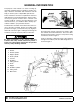
GENERAL INFORMATION The purpose of this manual is to assist in setting up, operating and maintaining your backhoe. Read it carefully. It furnishes information and instructions that will help you achieve years of dependable performance. These instructions have been compiled from extensive field experience and engineering data. Some information may be general in nature due to unknown and varying conditions.
SAFETY RULES ATTENTION! BECOME ALERT! YOUR SAFETY IS INVOLVED! Safety is a primary concern in the design and manufacture of our products. Unfortunately, our efforts to provide safe equipment can be wiped out by an operator’s single careless act. In addition to the design and configuration of equipment, hazard control and accident prevention are dependent upon the awareness, concern, judgement, and proper training of personnel involved in the operation, transport, maintenance, and storage of equipment.
SAFETY RULES ATTENTION! BECOME ALERT! YOUR SAFETY IS INVOLVED! (Safety Rules continued from previous page) Power unit must be equipped with ROPS or ROPS cab and seat belt. Keep seat belt securely fastened. Falling off power unit can result in death from being run over or crushed. Keep foldable ROPS system in “locked up” position at all times. Only mount this backhoe on Category 1 tractors with 800 lb. lift capacity at 24" behind 3-point lift arm hitch balls.
SAFETY RULES ATTENTION! BECOME ALERT! YOUR SAFETY IS INVOLVED! When operating controls, always sit in backhoe seat. Operate tractor PTO at 540 RPM. Do not exceed. Always dump spoil at least two feet away from opening. Use extreme care when working close to fences, ditches, other obstructions, or on hillsides. Be careful when swinging loaded bucket on a hillside. Always dump spoil on uphill side of backhoe to minimize the possibility of upset.
SAFETY & INSTRUCTIONAL DECALS ATTENTION! BECOME ALERT! YOUR SAFETY IS INVOLVED! Replace Immediately If Damaged! 1 - SERIAL NUMBER PLATE MODEL NO. SERIAL NO. Woods Equipment Company Oregon, Illinois, U.S.A. 5 - PN 1008365 WARNING 4 - PN 1011994 BH80-X Only 6 - PN 37885 7 - PN 37884 HIGH-PRESSURE HYDRAULIC OIL LEAKS CAN PENETRATE SKIN AND RESULT IN SEVERE INJURY, GANGRENE OR DEATH. FLOAT 8 - PN 33437 LOCK 33437-E 10 Safety 37885-A 37884-A Check for leaks with cardboard; never use hand.
SAFETY & INSTRUCTIONAL DECALS ATTENTION! BECOME ALERT! YOUR SAFETY IS INVOLVED! Replace Immediately If Damaged! 2 - PN 1011992 3 - PN 1011993 " BE CAREFUL! Use a clean, damp cloth to clean safety decals. Avoid spraying too close to decals when using a pressure washer; high-pressure water can enter through very small scratches or under edges of decals causing them to peel or come off. Replacement safety decals can be ordered free from your Woods dealer.
OPERATION The operator is responsible for the safe operation of the backhoe. The operator must be properly trained. Operators should be familiar with the backhoe, the tractor, and all safety practices before starting operation. Read the safety rules and safety decals on pages 7 to 11. DANGER Never put backhoe into service unless backhoe manufacturer's 3-point hitch Saf-T-Lok® limiter or sub-frame has been installed and adjusted.
Mechanical failures such as a hose rupture will cause a load to drop. Lifting a heavy load with the dipper, then operating the boom, could cause boom to drop. In either case, if anyone is in the operating area (maximum reach of bucket) as shown in Figure 1, serious injury or death could occur. Do not dig with backhoe unless stabilizers are down and on a firm surface.
After becoming familiar with the backhoe operation, practice coordinated use of the controls in a safe open area at reduced engine speed. Gradually increase engine speed as the technique is mastered. Operate backhoe gently and smoothly. Avoid swinging boom into mainframe. Sudden stopping or jerking could result in serious damage to tractor and backhoe. FILL BUCKET Control bucket attitude throughout digging cycle to keep teeth parallel to bottom of excavation.
Digging near center of swing so material may be dumped on either side will produce good results. Never dig near stabilizers. Continue the trench by moving machine along trench centerline away from existing excavation. Move machine approximately one-half the effective backhoe reach. Moving too far will require excessive down pressure for digging and hand clean-up of trench bottom. Figure 7. Level with Cut Out TRANSPORTING WARNING Figure 5.
3 Remove pin that attaches top link to tractor. Remove lower 3-point arms from backhoe. Place blocks under mainframe and raise stabilizers to lower backhoe mainframe onto blocks. Block backhoe as necessary to make it stable. 4 Disconnect hydraulic system. 4-Point Sub-Frame Mount Removal 4 NOTE: See the sub-frame mounting kit manual that fits your tractor for specific instructions. 1 1. 2. 3. 4.
NOTE: Circuit must be complete to prevent damage to tractor hydraulic system. Place thumb in operating position by selecting an appropriate pin location on the telescoping tube. Rotate the bucket to hold material against the thumb. When normal backhoe operation is required, place thumb in storage position. Remove pin, rotate thumb up against dipper, and insert pin to lock thumb into position.
NOTES 18 Operation (Rev.
OWNER SERVICE The information in this section is written for operators who possess basic mechanical skills. If you need help, your dealer has trained service technicians available. For your protection, read and follow the safety information in this manual. WARNING Keep hands and body away from pressurized lines. Use paper or cardboard, not hands or other body parts to check for leaks. Wear safety goggles. Hydraulic fluid under pressure can easily penetrate skin and will cause serious injury or death.
LUBRICATION It is recommended that all fittings be lubricated daily or every eight hours of operation. In very wet or dry conditions, lubricate every four hours of operation. WARNING Keep all persons away from operator control area while performing adjustments, service, or maintenance. Do not let excess grease collect on or around parts, particularly when operating in sandy areas. Figure 12 shows lubrication points for the backhoe. 1. 2. 3. 4. 5. 6. 7. 8. 9. 10. 11. 12. 13. 14. 15. 16. 17.
OPTIONAL HYDRAULIC PUMP SYSTEM CLEANING Daily, check the fluid level in reservoir with filler cap dipstick. Contamination will shorten the life of hydraulic system components. Change oil and filter after first 20 hours of operation and then every 200 hours of operation or annually, whichever occurs first. In extremely dusty or dry conditions, more frequent changes may be necessary. System capacity is approximately 5-1/2 to 6 U.S. gallons.
TROUBLESHOOTING PROBLEM Noisy pump caused by cavitation POSSIBLE CAUSE SOLUTION Oil too heavy Change to proper viscosity Oil filter plugged Replace filter Suction line plugged or too small Clean line and check for size Suction line kinked Replace line Oil supply low Fill reservoir Contaminated oil Drain reservoir, change filter, and refill with clean oil Setting of relief valve too high or too low Set to correct pressure Pump operating too fast Do not exceed 540 rpm PTO speed Shaft seal l
DEALER SERVICE The information in this section is written for dealer service personnel. The repair described here requires special skills and tools. If your shop is not properly equipped or your mechanics are not properly trained in this type of repair, it may be more time and cost effective to replace complete assemblies. WARNING Adjustment of system relief pressure must be done by a qualified, experienced dealership. Incorrect adjustment can result in system failures and serious personal injury.
a large screwdriver. Inspect seat in valve housing for any dirt or damage. Replace load check if required. Spool Repair Carefully inspect spool bore in valve housing. If deep scratches or scouring is present, entire valve should be replaced. Assemble Whenever repairing spools or positioner, replace valve spool seals which are included in the spool seal repair kit. Disassemble Remove the joystick assembly and/or single lever control from valve. Remove the plastic dust cap from positioner (5, 6).
ADJUST CONTROL VALVE LINKAGE Reconnect control linkage to valve. Control handles should be positioned as shown. When completing a maintenance function on the valve, perform a functional test by placing control handles in their various positions and make certain the correct operation occurs corresponding to the decals on the operator's console. Pay specific attention to the float position of the boom. Do not operate backhoe if functions differ from the decal.
13 lbs-ft. in an alternating sequence. Non-uniform or excessive tightening can cause binding of spools. Fail- ure to attain the proper torque can result in leaks. Always use a torque wrench. Figure 15.
1. Complete hydraulic valve 2. Left stabilizer segment 3. Check valve assembly a. Poppet b. Spring c. Seal d. Car plug 4AA. Shock/dampening valve, 2470 psi 4BB. Shock/dampening valve, 2610 psi a. Cap nut b. Washer c. Adjusting screw d. Retainer e. Rear spring washer f. Copper washer g. Spring for relief valve h. Front spring washer i. Valve poppet j. Back-up ring k. Seal l. Valve seat m. Back-up ring n. Washer o. Ball, Dia. 5 6. 1350 - 3000 Psi Relief valve assembly a. Cap nut b. Copper washer c.
HYDRAULIC CYLINDER REPAIR General Hydraulic Repair Information The only repair parts available for these cylinders are seal kits. If damage occurs to one of the cylinder components, replace the cylinder. NOTE: Before ordering seal kits, check stamping on barrel. Part numbers ending with either "E" or "J" require specific seal kits. See parts page 45 for correct seal kit number. A clean working area is essential for any hydraulic repair. All parts must be carefully cleaned before reassembly.
Disassemble Disassemble Remove snap ring (3) from end of barrel. Slide rod assembly out of barrel. Inspect inside of cylinder barrel and rod surface for any scratches or scouring. Small scratches can be removed with fine crocus cloth. If scratches cannot be repaired, replace entire cylinder. Check for style of rod guide and follow instructions in corresponding section. Slide rod assembly out of barrel. Inspect inside of cylinder barrel and rod surface for any scratches or scouring.
ASSEMBLY GENERAL ASSEMBLY INSTRUCTIONS Backhoe assembly is the responsibility of the WOODS dealer. The backhoe should be delivered to the owner completely assembled, lubricated and adjusted for normal operating conditions. Set backhoe up as received from the factory with these instructions and illustrations. The backhoe must only be mounted with a tractor 3point hitch using WOODS 3-Point Mount kit or a WOODS sub-frame kit. See WOODS 3-Point Mount manual for mount installation instructions.
1. 2. 3. 4. 5. 6. 7. 8. 10. Bucket 1 x 7.12" Pin 5/16 x 2-1/2" Bolt 5/16" Lock nut Bucket link Dipper Boom Dipper cylinder 1.12 x 5.5" Headless pin Figure 20. Dipper and Bucket Installation (Typical Assembly) DIPPER CYLINDER INSTALLATION Remove pivot pin (10) from end of dipper (6). Attach dipper cylinder (8) to dipper (6) with pivot pin and secure with bolt (3) and lock nut (4). Make sure hydraulic hoses are not twisted after boom and dipper are assembled.
tings securely. Start engine and run at low rpm. Activate hydraulic circuit and check for leaks. NOTE: Use thread sealant on all pipe fittings. Install hydraulic reservoir (1) to backhoe mainframe with carriage bolts (7) and flange lock nuts (8). Attach elbow (3) to the outlet side of the filter assembly (4). Make sure elbow points downward. Attach adapter (6) and hose (23) to the inlet side of the filter assembly. Attach assembly to top of reservoir with elbow (3).
1. 2. 3. 4 6. 7. 8. 9. 10. 11. 12. 13. 14. Tank Breather cap w/dipstick Elbow, 3/4 NPTM x 3/4 NPSM Filter & housing assembly Adapter, 1/2 NPTF x 3/4 NPTM 3/8 NC x 3/4 Carriage bolt 3/8 Flange lock nut Tank strainer Adapter, 1-1/4 NPTM x 3/4 NPTF Elbow, 3/4 hose 90° 1/2 Hose clamp Hose, 3/4 x 36" Fitting, 90° 15. 16. 17. 18. 19. 20. 23. 24.
PUMP MOUNTING BRACKET INSTALLATION DANGER The only time the backhoe may be operated from a position other than the operator seat is during backhoe attachment and removal. Operator must: • Read Mounting Kit Manual instructions on attaching and removing backhoe and use extreme care. • Always stand between rear tire and backhoe stabilizer arms or along side of tractor to avoid being trapped should the boom swing control be accidentally activated.
DEALER CHECK LIST PRE-DELIVERY CHECK LIST (DEALER’S RESPONSIBILITY) DELIVERY CHECK LIST (DEALER’S RESPONSIBILITY) Inspect the backhoe (and sub-frame when applicable) thoroughly after assembly to be certain it is set up properly before delivering it to the customer. The check lists are a reminder of points to inspect. Check off each item as it is found satisfactory or after proper adjustments are made.
NOTES 36 Dealer Check Lists MAN0450 (10/28/2005)
PARTS INDEX BH70-X and BH80-X BH70-X & BH80-X MAIN FRAME ASSEMBLY . . . . . . . . . . . . . . . . . . . . . . . . . . . . 38 BOOM ASSEMBLY . . . . . . . . . . . . . . . . . . . . . . . . . . . . . . . . . . . . . . . . . . . . . . . . . 40 DIPPER/BUCKET ASSEMBLY . . . . . . . . . . . . . . . . . . . . . . . . . . . . . . . . . . . . . . . . 41 BH70-X CONTROL VALVE ASSEMBLY . . . . . . . . . . . . . . . . . . . . . . . . . . . . . . . . . 42 BH80-X CONTROL VALVE ASSEMBLY . . . . . . . . . . . . . . . . . . .
BH70-X, BH80-X MAIN FRAME ASSEMBLY 38 Parts MAN0450 (10/28/2005)
BH70-X, BH80-X MAIN FRAME ASSEMBLY PARTS LIST REF PART QTY DESCRIPTION REF PART QTY DESCRIPTION 1 1003828 1 Manual tube 40 7251 2 5/16 x 2 Spring pin 3 1011800 1 Main frame 41 78205 * 4 5/16 NC x 3/4 HHCS GR5 4 1011821 1 Trunnion support bar (also order 2 of item 21) 42 6250 * 5 5/16 x 1-1/4 HHCS GR5 43 1008291 * 3 5 1030003 2 Hydraulic cylinder, 2.5 x 1.5 x 11.0 5/16 NC x 2-1/2 Carriage bolt GR5 (BH70-X) 6 1030005 2 Hydraulic cylinder, 2.0 x 1.125 x 9.
BH70-X, BH80-X BOOM ASSEMBLY REF PART QTY DESCRIPTION REF PART QTY DESCRIPTION 2 1030006 1 Hydraulic cylinder 2.5 x 1.25 x 15.50 Retracted length 26.25" (BH80-X) -or- 11 1011920 1 Boom (BH80-X) -or- 11 1011980 1 Boom (BH70-X) 2 1030009 1 Hydraulic cylinder 2.5 x 1.25 x 15.50 Retracted length 23.38" (BH70-X) 12 2 5/16 NC x 2-1/2 HHCS GR5 3 1030007 1 Hydraulic cylinder 2.5 x 1.38 x 19.38 (BH80-X) -or- 13 14562 * 2 5/16 NC x 1 HHCS GR5 14 37429 2 Bearing, 1.25 x 1.41 x 1.
BH70-X, BH80-X DIPPER/BUCKET ASSEMBLY REF A PART QTY DESCRIPTION REF PART QTY DESCRIPTION 1014209 1 Bucket, 9" -or- 10 10509 * 3 5/16 NC x 2-1/2 HHCS GR5 1014212 1 Bucket, 12" -or- 11 24576 * 2 1014216 1 Bucket, 16" -or- 1/2 NC x 1-3/4 HHCS GR5 (used w/bucket tooth 1014202) -or- 1014218 1 Bucket, 18" -or- 11 10978 * 2 1014224 1 Bucket, 24" 7/16 NC x 1-3/4 HHCS GR5 (used w/bucket tooth D1070) 1 1030008 1 Hydraulic cylinder, 2.5 x 1.25 x 13.
BH70-X CONTROL VALVE ASSEMBLY REF PART QTY DESCRIPTION REF 8 PART QTY DESCRIPTION A 1011951 1 6-Spool control valve 2030 psi MBLK 1 1011953 1 4-Position float spool 2 1011954 5 3-Position spool 9 38631-1 2 Plug port relief cavity 38632-1 2 Plug, 3/4 SAE male w/O-ring 53381 3 Valve relief 2470 psi w/anti-cavitation check 3 33343 1 Spool, 4-position control assembly 10 4 1011955 5 Spool, 3-position control assembly 11 33339 6 Valve, load check assembly 5 38628-1 2
BH80-X CONTROL VALVE ASSEMBLY REF MAN0450 (10/28/2005) PART QTY DESCRIPTION 1 1011952 1 Control valve assembly 2 53380 2 Port relief valve 2610 psi 3 53381 3 Port relief valve/anti-cav 2470 psi 4 38631-1 1 Plug, port relief cavity 5 33343 1 Spool position control assembly 6 33345 5 Spool position control assembly 7 38622 1 Valve inlet section 8 30515 8 8mm x 1.25P Hex nut 9 33440 3 8mm x 1.
CONTROL VALVE HARDWARE BH70-X REF A PART QTY ----- 3 DESCRIPTION BH80-X REF PART QTY DESCRIPTION Spool wiper (included w/item1) A 1011952 1 Valve, 6 spool sectional 2470 psi 1 1011951 1 Valve, 6 spool monoblock 2030 psi 1 37573 2 Control handle 2 1008321 1 Plate, control linkage mounting 2 37613 6 5/16 NF Female rod end 3 1008322 2 Sleeve .325 x .463 x .680 3 37556 2 Valve mounting bracket 4 1011865 1 Control handle 7 37548 2 16 GA x .36 x .67 x .
HYDRAULIC CYLINDERS NOTE: Before ordering seal kits, check stamping on barrel near base end port. 1. If an "E" is stamped on barrel, use part number’s in Table 1, column "E". 2. If a "J" is stamped on the barrel, check Woods part number of the complete assembly stamped on the barrel. Locate that part number in Table 1 or Table 2 and order seal kit from the "J" column. Table 1 Complete Assembly Base End Style Retracted Length Bore Dia Rod Dia Swing 1011825 Trunnion 4.50 2.00 1.
BH70-X HOSES & FITTINGS HOSE REF PART 1 62367 2 1011814 QTY DESCRIPTION 15 9/16-18 to O-ring connector 2 Adapter, 9/16 JICM x 9/16 ORBM restricted .063 3 1011816 1 Adapter, 9/16 JICM x 9/16 ORBM restricted .082 (green) 4 37508 1 Adapter, 9/16 JICM x 9/16 ORBM Restricted .
BH80-X HOSES & FITTINGS HOSE REF PART QTY 1 DESCRIPTION Valve flow control REF PART QTY DESCRIPTION 1 1012510 A 1014241 1 Hose, 1/4 42" 9/16 JICF 9/16 JICF 2 62367 16 Adapter, 9/16 ORBM x 9/16 JICM B 1014240 1 Hose, 1/4 42" 9/16 JICM 9/16 JICF 3 38605 4 Adapter, 9/16 ORBM x 9/16 JICM long C 1014247 1 Hose, 3/8 135" 9/16 JICF 9/16 JICF D 1014246 1 Hose, 3/8 124" 9/16 JICF 9/16 JICF 4 1011816 1 Adapter, 9/16 JICM x 9/16 ORBM restricted .
BH70-X & BH80-X THUMB ASSEMBLY (OPTIONAL) REF PART QTY DESCRIPTION 1 1012609 1 Pin, hitch 1.25 x 4.25 2 1031510 1 Thumb, BH70-X / BH80-X 4 1016405 1 Inner tube, BH70-X -or- 4 1015109 1 Inner tube, BH80-X 5 1016403 1 Outer tube, BH70-X -or- 5 1015111 1 Outer tube, BH80-X 7 1015115 1 Clevis pin, 1.0 x 10.69 8 300105 * 3 5/16 NC x 2 Hex head cap screw GR5 10 55242 2 Pin, 1.0 x 5.
BH70-X, BH80-X PUMP & TANK ASSEMBLY (OPTIONAL) REF PART QTY 1 1012590 1 Tank, 13.31 x 15.0 x 21.25 13 31210 1 Hose, 3/4 x 36" 2 31414 1 Breather cap with dipstick 14 62429 1 Elbow, 90° 3 1012559 1 Elbow, 3/4 NPTF x 3/4 NPSM 15 62428 1 Adapter, 1-5/16 ORBF x 1-5/16 ORBM 4 62420 1 Filter & housing assembly 16 37909 1 Pump, 2.
BOLT TORQUE CHART Always tighten hardware to these values unless a different torque value or tightening procedure is listed for a specific application. Fasteners must always be replaced with the same grade as specified in the manual parts list. Always use the proper tool for tightening hardware: SAE for SAE hardware and Metric for metric hardware. Make sure fastener threads are clean and you start thread engagement properly.
BOLT SIZE CHART NOTE: Chart shows bolt thread sizes and corresponding head (wrench) sizes for standard SAE and metric bolts. SAE Bolt Thread Sizes 5/16 3/8 1/2 IN MM 5/8 3/4 7/8 1 2 3 4 5 6 7 25 50 75 100 125 150 175 Metric Bolt Thread Sizes 8MM 10MM 12MM 14MM 16MM 18MM ABBREVIATIONS AG ............................................................. Agriculture ATF...............................Automatic Transmission Fluid BSPP ..........................
INDEX Bolt Size Chart 51 Bolt Torque Chart 50 General Information 6 Introduction 2 Obtaining Replacement Manuals Product Registration 2 Specifications 4 Table of Contents 3 Warranty Product 53 Replacement Parts 54 A Assembly Attaching Backhoe to Tractor 33 Bucket Installation 31 Dipper Installation 31 General Assembly Instructions 30 Hydraulic Installation 31 Open-Center 31 Hydraulic Pump Installation 32 Install Optional Stabilizer Street Pad 34 Optional Equipment 3-Point Mount Kit 34 Mechanical Thumb (BH7
WARRANTY (All Models Except Mow’n MachineTM Zero-Turn Mowers and Woods BoundaryTM Utility Vehicles) Please Enter Information Below and Save for Future Reference. Date Purchased: ____________________________ From (Dealer): __________________________________________ Model Number: ____________________________ Serial Number: __________________________________________ Woods Equipment Company (“WOODS”) warrants this product to be free from defect in material and workmanship.
WARRANTY (Replacement Parts For All Models Except Mow’n MachineTM Zero-Turn Mowers and Woods BoundaryTM Utility Vehicles) Woods Equipment Company (“WOODS”) warrants this product to be free from defect in material and workmanship for a period of ninety (90) days from the date of delivery of the product to the original purchaser with the exception of V-belts, which will be free of defect in material and workmanship for a period of 12 months.