(Rev.
TO THE DEALER: Assembly and proper installation of this product is the responsibility of the Woods® dealer. Read manual instructions and safety rules. Make sure all items on the Dealer’s Pre-Delivery and Delivery Check Lists in the Operator’s Manual are completed before releasing equipment to the owner. The dealer must complete the online Product Registration form at the Woods Dealer Website which certifies that all Dealer Check List items have been completed.
TABLE OF CONTENTS INTRODUCTION . . . . . . . . . . . . . . . . . . . . . . . . . . . . . . . . . . . . . . . . . . . . . . .2 SPECIFICATIONS. . . . . . . . . . . . . . . . . . . . . . . . . . . . . . . . . . . . . . . . . . . . . .4 BALANCE STATEMENT . . . . . . . . . . . . . . . . . . . . . . . . . . . . . . . . . . . . . . . . .5 GENERAL INFORMATION . . . . . . . . . . . . . . . . . . . . . . . . . . . . . . . . . . . . . . .5 SAFETY RULES . . . . . . . . . . . . . . . . . . . . . . . . . . . . . . . . .
SPECIFICATIONS Maximum Outside Body Width: 15′ . . . . . . . . . . . . . . . . . . 189 in. (4.9 m) 20′ . . . . . . . . . . . . . . . . . . 253 in. (6.4 m) 22′ . . . . . . . . . . . . . . . . . . 277 in. (7.0 m) 25′ . . . . . . . . . . . . . . . . . . 309 in. (7.8 m) 27′ . . . . . . . . . . . . . . . . . . 334 in. (8.4 m) Cutting Height: . . . . . . . . . . . . . . . . . . . . 3 - 18 in. (7.62 cm to 45.7 cm) Width of Cut: 15′ . . . . . . . . . . . . . . . . . . 183 in. (4.6 m) 20′ . . . . . . . . . . . . . .
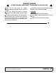
IMPORTANT! BALANCE STATEMENT Both of the Woods Center Drive Shredder flail tubes are balanced as rotor assemblies to meet or exceed factory standards before installation. After installation, the shredders are statistically inspected to check balance. These factory efforts allow the shredder to operate smoothly and be free of excessive vibration when delivered to the customer. WARNING wear unevenly. This can reduce their chopping effect and also increase vibration levels.
SAFETY RULES ATTENTION! BECOME ALERT! YOUR SAFETY IS INVOLVED! Safety is a primary concern in the design and manufacture of our products. Unfortunately, our efforts to provide safe equipment can be wiped out by an operator’s single careless act. In addition to the design and configuration of equipment, hazard control and accident prevention are dependent upon the awareness, concern, judgement, and proper training of personnel involved in the operation, transport, maintenance and storage of equipment.
SAFETY RULES ATTENTION! BECOME ALERT! YOUR SAFETY IS INVOLVED! Connect PTO driveline directly to power unit PTO shaft. Never use adapter sleeves or adapter shafts. Adapters can cause driveline failures due to incorrect spline or incorrect operating length and can result in personal injury or death. Inspect rubber flaps and swing rod before each use. Replace if damaged or missing. Flaps must pivot and hang freely so there are no gaps. Do not put equipment into service until repaired.
SAFETY RULES ATTENTION! BECOME ALERT! YOUR SAFETY IS INVOLVED! (Safety Rules continued from previous page) Look down and to the rear and make sure area is clear before operating in reverse. Do not operate or transport on steep slopes. Do not stop, start, or change directions suddenly on slopes. Use extreme care and reduce ground speed on slopes and rough terrain. Watch for hidden hazards on the terrain during operation. Stop power unit and equipment immediately upon striking an obstruction.
SAFETY RULES ATTENTION! BECOME ALERT! YOUR SAFETY IS INVOLVED! Make sure all safety decals are installed. Replace if damaged. (See Safety Decals section for location.) Leak down or failure of mechanical or hydraulic system can cause equipment to drop. Make sure shields and guards are properly installed and in good condition. Replace if damaged.
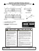
SAFETY & INSTRUCTIONAL DECALS ATTENTION! BECOME ALERT! YOUR SAFETY IS INVOLVED! Replace Immediately If Damaged! 1 - YELLOW REFLECTOR PN 20034004 3 - SERIAL NUMBER PLATE 2 - RED REFLECTOR PN 57123 4 - RED-ORANGE FLUORESCENT MATERIAL PN 20034034 MODEL NO. SERIAL NO. Woods Equipment Company Oregon, Illinois, U.S.A. 5 - PN 50030977 CAUTION PRECAUCION 1. Read Operator's Manual before starting. 1. Lea el Manual del Operario antes de empezar. 2.
SAFETY & INSTRUCTIONAL DECALS ATTENTION! BECOME ALERT! YOUR SAFETY IS INVOLVED! Replace Immediately If Damaged! DANGER PELIGRO DANGER PELIGRO ROTATING FLAIL HAZARD ROTATING DRIVELINE HAZARD To prevent serious injury or death from rotating flails: 1. Stop engine, remove ignition key, and wait for moving parts to stop before servicing. 2. Keep hands and feet away from flails when engine is running. 3. Keep other people away. To prevent serious injury or death from rotating driveline: 1.
SAFETY & INSTRUCTIONAL DECALS ATTENTION! BECOME ALERT! YOUR SAFETY IS INVOLVED! Replace Immediately If Damaged! (Safety Decals continued from previous page) 12 - PN 50530728 11 - PN 50530707 WARNING ADVERTENCIA 14 - PN 50530315 16 - PN 33347 15 - PN 18864 HIGH-PRESSURE FLUID HAZARD To prevent serious injury or death: 1. Relieve pressure on system before repairing, adjusting, or disconnecting. 2. Wear proper hand and eye protection when searching for leaks. Use wood or cardboard instead of hands. 3.
OPERATOR SIGN-OFF RECORD Woods Equipment Company follows the general safety standards specified by the American Society of Agricultural and Biological Engineers (ASABE) and the Occupational Safety and Health Administration (OSHA) for agricultural equipment. Anyone who will be operating and/or maintaining the flail shredder must read and clearly understand all Safety, Operating, and Service & Maintenance information presented in this manual.
OPERATION The Woods Flail Shredder is designed to pick up and shred crop and plant residue left in the field. Rotational power to the flails is provided by the tractor PTO. Be familiar with the flail shredder before starting. The owner is responsible for training operators in the safe operation of the flail shredder. WARNING Safety instructions are important! Read all attachment and power unit manuals; follow all safety rules and safety decal information.
1. Crossmember 2. Rubber belt shield 3. Skid assembly 4. Rubber belt shield 5. Body weldment 6. Flail tube assembly RH 7. Flail tube assembly LH 8. Woods model decal 9. Gearbox 10. Bearing assembly Figure 1. Flail Shredder Principal Components PRE-OPERATION CHECK LIST (OWNER'S RESPONSIBILITY) NOTICE ■ This Pre-Operation Check List is provided for the operator. It is important to follow for both personal safety and maintenance of the flail shredder.
Table 1: Tractor Horsepower (6-8) vs. Unit Width Width Minimum Horsepower 6. Drawbar (Pull-Type Models Only) The tractor drawbar must be set to provide 16" (406 mm) on 1-3/8 - 21 or 20" (508 mm) 1-3/4 - 20 between the end of the PTO shaft and the center of the drawbar pin for all 1000 rpm PTO. See Figure 4. This dimension will provide the required clearance for the CV (Constant Velocity) joint on the front of the driveline. 15′ 90 20′ 120 22′ 132 25′ 150 ■ Do not use PTO shaft adapters.
ATTACHING SHREDDER TO TRACTOR WARNING 1. Place unit on a level, dry area free of debris and other foreign object. Keep bystanders away from equipment. WARNING 1. Clear the area of all bystanders. 2. Attach the 3-point hitch to the unit but not the PTO driveline. 3. Raise the unit until the tractor PTO and gearbox shafts are the same height. 4. Measure the dimension between the shaft grooves on the tractor and implement ends. If this dimension is less than 34.
Without Quick Hitch Attachment: 1. Back tractor lower 3-point arms between lower mast plates and align with lower 3-point hole. 2. Place 1-3/4 OD spacer through 3-point arm pivot (both sides). 3. Push tractor’s 3-point arm to the inside and slide a 1-7/16 OD spacer between to take up the empty space. Secure with lower 3-point hitch pin assembly, 1-3/4 OD spacer, and 7/16 x 2 klik pin. 4. Repeat steps 5 and 6 for other side. 5.
Raise Stands 1. Use hitch ratchets or 3-point hitch to raise the front of the machine. 2. Unpin front frame stands. Raise and pin in their upper position. See Figure 10. REMOVING SHREDDER FROM TRACTOR Reverse the above procedure (Steps 1-17) when removing unit from the tractor. Keep hands, feet, hair, and clothing away from equipment while engine is running. Stay clear of all moving parts.
the flails under all operating conditions. (See Balance Statement, page 5.) NOTE: To avoid unnecessary wear on knives and related parts, never set the unit lower than the recommended setting. (See Balance Statement, page 5.) 4. 3-Point models only: Be sure the floating mast is free to slide in its mounting frame to allow the machine to follow ground contours. Refer to Figure 13. Floating Top Mast 7109 7111 Figure 11. 3-Point Hitch Models Figure 13.
Setting Outer Trailing Wheels (Casters & Struts) . Normally, wheels are set to track in the row centers, between the raised seed beds. Tire position will determine flail height, but depth of furrow is also a factor in setting flail height. In some conditions the furrow between the seed beds is deeper on the ends, where irrigation waters enter the field. As furrows change depth, flail height will change. Figure 14.
HAZARD AREA WARNING Make certain all movement of equipment components has stopped before approaching for service. CV joint angle should not exceed 80 degrees in either operating or standstill condition of the driveline. Larger angles will damage the joint. The angle should never exceed 35 degrees when the driveline is under full load. NOTICE ■ Disengage PTO when making sharp turns. Stay away from front, side, and rear of unit while it is running.
● Replace any safety decals that are missing or not readable (supplied free by your Woods dealer). See Safety Decals section for location drawing. 12. Do not allow children to play on or around the stored unit. OPTIONAL EQUIPMENT STORAGE WARNING Block equipment securely for storage. Keep children and bystanders away from storage area. RUBBER FLAPS All units are equipped with front shield flaps (Figure 20) along the front of the frame.
SERVICE & MAINTENANCE WARNING Before dismounting power unit or performing any service or maintenance, follow these steps: disengage power to equipment, lower the 3-point hitch and all raised components to the ground, operate valve levers to release any hydraulic pressure, set parking brake, stop engine, remove key, and unfasten seat belt. Before working underneath, read manual instructions, securely block up, and check stability.
Figure 22. PTO Driveline Lubrication Points A. Daily or 8 hours B. 25 hours C. 40 hours D. Check Daily/Change Annually Figure 23. Lubrication Points (Rev. 1/24/2011) MAN0506 (Rev.
Every 40 hours of operation Daily or every 8 hours of operation 1. Lubricate PTO U-joints and over-running clutch. 2. Check gearbox daily or every 8 hours of operation. See Figure 24 for gearbox oil fill location. 1. Lubricate rotor drive couplers next to the couplers on underside of unit and inside of flail tube (use hole in flail tube to access grease fitting, 2 locations). 2. Grease the drive hubs with 10 to 20 pumps. You may use extra grease only on drive hubs. Annually 1. Change gearbox oil.
LUBRICATION SERVICE RECORD NOTE: See page 24 through page 27 for details. Copy this page to continue service record. HOURS OF SERVICE SERVICED BY 10 Hours or daily L PTO Driveline (8) L PTO Driveline telescope section L U-Joint (1) L Overrunning clutch (1) ✔ Gearbox oil level 25 Hours L Rotor end bearings L Wheel mounting tube bearings 40 Hours L Rotor inner bearings (2) Annually C Gearbox oil R Wheel bearings L Ratchets NOTICE GEARBOX OIL LEAKAGE ■ DO NOT OVERFILL.
Gearbox leakage & Troubleshooting Some gearbox oil leakage may be acceptable if: 1. Oil covers less than a 3-inch diameter circle around the shaft seal area (see Figure 30). 2. Oil covers less than a 4-inch diameter circle around the dipstick tube (see Figure 30). If oil leakage covers an area larger than that described in 1 and 2, do the following: 1. Properly check oil level. If low, properly service. 2. Clean oily area of gearbox. Use a degreaser to remove all oil from outside surface of gearbox. 3.
2. Shut off tractor, place all controls in neutral, set parking brake, remove key, and wait for all moving parts to stop. 3. Use a jack with sufficient capacity to lift the frame. 4. To determine wheel spacing, measure from the center line of the unit. Mark positions on the frame. 5. Lift frame until wheels have cleared the ground. 6. Place safety stands or large blocks under the frame. 7. Loosen mounting bolts on one wheel assembly. DRAIN PLUG Figure 31. Drain Plug (Underside of Unit) 8.
3. Disconnect driveline and hydraulic lines from the tractor. 4. Place safety stands or large blocks under the frame. 5. Loosen and remove the worn flail and its opposite on the other side of the rotor. Discard worn flails and their mounting hardware. 6. Replace with new flails and mounting hardware (see Figure 34). Figure 35. Front Rubber Shield Flaps 4. Replace damaged flap with new flap and secure with correct hardware. NOTE: Use only genuine Woods parts when replacing flaps.
Technical Service for re-balance options or further details. LOCKING COLLAR SET SCREW LOCKING COLLAR Follow the procedure below if rotor removal or replacement is required. Use a suitable lifting device of sufficient capacity. Use adequate personnel to handle heavy components. 1. Clear the area of any bystanders. FOR REMOVAL: TAP WITH A HAMMER AND PUNCH AFTER LOOSENING SET SCREW. FOR INSTALLATION: REVERSE PROCEDURE MAN0506003 2.
REPLACING STUB SHAFT 1. Remove rotor (see Servicing Rotors (Flail Tubes), page 30). 2. Remove three 1/2 x 2-1/2 hex bolts in taper lock hub and re-install bolts in three threaded holes (see Figure 38). 3. Tighten bolts evenly to release taper lock hub from stub shaft. NOTE: You may have to give a sharp blow directly to each bolt head to help the hub disengage. 4. Unscrew stub shaft from the rotor tube. Figure 37. Rotor Direction of Rotation 5. Install new stub shaft, reversing Steps 1-3. Figure 38.
NOTE: The shaft is heavy. Grasp the clutch firmly with both hands and slide off the input shaft. Rebuilding Friction Pack Inspection 1. Inspect the steel parts for wear and replace if necessary. 2. Inspect the yoke/hub for looseness. If there is more than .03 end play, replace. Disassembly 1. Position clutch and universal joint assembly on a bench so that end is accessible. 2. Remove the long bolts on the outside of the housing that hold the friction pack together. 3.
NOTES 34 Service & Maintenance MAN0506 (Rev.
TROUBLESHOOTING The Woods Flail Shredder uses swinging flails to pick up and shred crop residue left in the field. It is a simple and reliable system that requires minimal maintenance. The following table lists problems, causes, and solutions that you may encounter. If you encounter a problem that is difficult to solve even after reading through this table, please call your local Woods dealer. When calling, please have this manual and your unit’s serial number ready.
WORKSHEET FOR CONTOUR FLAIL PATTERNS 36 Contour Flail Patterns MAN0506 (Rev.
WORKSHEET FOR CONTOUR FLAIL PATTERNS 24’ MAN0506 (Rev.
ASSEMBLY DEALER SET-UP INSTRUCTIONS WARNING After the unit has been leveled for a couple of hours, check oil level and service through the dipstick/filler tube as required. Do not allow bystanders in the area when operating, attaching, removing, assembling, or servicing equipment. Do not handle knives with bare hands. Careless or improper handling may result in serious injury. Keep hands and body away from pressurized lines. Use paper or cardboard, not hands or other body parts to check for leaks.
7. Attach front top link spacer, bolts, and lock nuts to front of upper mast assembly. 3. Install front parking stands (Figure 44), using L-pin and hair pin cotter. NOTE: For Quick Hitch Cat II, use spacer in front lower hole of upper mast assembly. For Quick Hitch Cat III, use spacer in front upper hole of upper mast assembly. Without Quick Hitch, use spacer through top link pivot in front upper hole of upper mast assembly. 8.
MANUAL STORAGE TUBE INSTALLATION The manual storage tube may be supplied in either of the following styles. For One-Piece Style Manual Tube: Mount the manual tube to the inside of the shredder side sheet, using three 3/8 x 1-1/4" hex bolts, washers, and 3/8" nuts. Mounting holes are located above the bearing plate (see Figure 46). NOTE: Use equal number of belting and bars on each side of shredder. 3. Tighten all hardware. RUBBER FLAP INSTALLATION 1. Remove all components from shipping carton.
provided. Make sure that light lenses are in the correct position in relation to direction of equipment travel: amber lenses on the outside, red lenses on the inside facing rear of shredder. 3. Install light bracket on end of shredder using 1/2 NC x 1-1/2" hex bolts, washers and nuts (four each) in slots 3 and 4 on top of end sheet. 4. Plug ends of wiring harness into corresponding plugs of the light units (Note: left side of wishbone harness is labeled “Left”). 5.
CENTER CUT KIT INSTALLATION 2. Install adapter (23) and hose (11) to the OUT or RETURN side of the motor. Block Shredded 3. Place motor (4) inside motor housing (2) and secure using six 9/16 NC x 1-1/2 cap screws (7) lock nuts (6). Make sure OUT or RETRUN side of motor is on the open side of the motor housing. Torque hardware to 171 lbs-ft. WARNING Never go underneath equipment (lowered to the ground or raised) unless it is properly blocked and secured.
Install Motor Housing 1. Slide motor assembly between shredder center channel and secure to the left side using two 1/2 NC x 1-1/4 carriage bolts (29) and flange lock nuts (30). 4. Place hose assembly around center plate of shredder and drape quick couplers over the front of the shredder. See Figure 55 and Figure 56. 5. Make sure hose with check valve is on the right side of the center plate. 2.
Install Hose Clamps Connect Hoses to Tractor 1. Place hose clamps (36) around hoses (11) and center hoses between center plate. 2. Mark clamp holes in desired location on shedder body and drill two 11/32" holes. 3. Secure hose clamps to shredder using 5/16 NF x 1-1/4 cap screws (20), flat washers (33), lock washers (34) and hex nuts (35). See Figure 57. NOTICE ■ Oil flow to hydraulic motor must not exceed 28 gpm. 1.
DEALER CHECK LISTS PRE-DELIVERY CHECK LIST (DEALER’S RESPONSIBILITY) Inspect the equipment thoroughly after assembly to make sure that it is set up properly before delivering it to the customer. The following check lists are a reminder of points to inspect. Check off each item as it is found satisfactory or after proper adjustment is made. ___ Check that all safety decals are installed and in good condition. Replace if damaged. ___ Properly attach implement to tractor and make all necessary adjustments.
NOTES 46 Dealer Check Lists MAN0506 (Rev.
PARTS INDEX FLAIL SHREDDER Center Drive FRAME ASSEMBLY . . . . . . . . . . . . . . . . . . . . . . . . . . . . . . . . . . . . 48-48 FLAIL TUBE ASSEMBLY . . . . . . . . . . . . . . . . . . . . . . . . . . . . . . . . . . .50 WHEEL ASSEMBLY . . . . . . . . . . . . . . . . . . . . . . . . . . . . . . . . . . . . . . .51 BED CONE ASSEMBLY (OPTIONAL) . . . . . . . . . . . . . . . . . . . . . . . . .52 WEASLER® PTO SHAFT WITH TORQMASTER CLUTCH 24K PULL-TYPE . . . . . . . . . . . . . . . . . . . . . . . . . . . .
CENTER DRIVE FLAIL SHREDDER FRAME ASSEMBLY 48 Parts MAN0506 (Rev.
CENTER DRIVE FLAIL SHREDDER FRAME ASSEMBLY PARTS LIST REF 1 1 1 1 1 2 PART QTY NSS NSS NSS NSS NSS ---------- 1 1 1 1 1 - 3 1016168 3 1013097 3 1016167 3 1013057 3 1013122 5 90507112 6 1012170 7 1010120 8 56383 9 50520211 10 50530279 14 1013049 16 1016104 16 1016105 16 1016106 16 1016107 16 1016108 16 1016109 17 20 21 22 24 24a 25 27 29 30 31 32 33 34 1012175 90025004 90025012 20020705 20020553 90029204 90006143 1019786 1019755 12735 90023084 230 90001786 90011015 * * * * * * * * DESCRIP
FLAIL TUBE ASSEMBLY REF LEFT PART # RIGHT PART # QTY DESCRIPTION 15’ Flail tube w/knives 15’ HD Cotton tube w/knives 15’ Cup knife tube w/knives 20’ Flail tube w/knives 20’ HD Cotton tube w/knives 20’ Cup knife tube w/knives 22’ Flail tube w/knives 22’ HD Cotton tube w/knives 22’ Cup knife tube w/knives 25’ Flail tube w/knives 25’ HD Cotton tube w/knives 25’ Cup knife tube w/knives 27’ Flail tube w/knives 27’ HD Cotton tube w/knives 27’ Cup knife tube w/knives 1 1 1016199LK 1016198LK 1016199HD 101619
WHEEL ASSEMBLY REF 1 PART NO 90509009 QTY 1 DESCRIPTION REF PART NO QTY DESCRIPTION Dust cap 16 50520111 1 Strut weldment 2 90109002 1 Seal 16 50520112 1 Strut assembly with hubs 3 90101023 1 Inner bearing cone 17 1010013 1 Caster arm assembly (8 holes) 4 90101022 1 Inner cup 18 50520197 1 Caster weldment 5 90509011 5 1/2 NF Wheel nut 18 50520198 1 Caster and hub assembly 6 90509003 1 Hub, 5-bolt 19 1010014 1 Back plate (8 holes) 7 90101016 1 Outer
BED CONE ASSEMBLY (OPTIONAL) 50510065 REF PART NO QTY DESCRIPTION 1 20031440 1 2 2377 6 U-Bolt, 3/4 NC x 4 x 5.
TYPE B - WEASLER® 24K PULL-TYPE PTO SHAFT WITH TORQMASTER CLUTCH REF PART NO QTY DESCRIPTION REF 1 PTO complete 1-3/8 21 spline -or- 10 1010819 1 Outer guard & bearing PTO complete 1-3/4 20 spline 11 1010820 1 Inner guard & bearing Slide lock repair kit 1.38 ID -or- 12 33347 1 Decal, Danger, Guard missing Slide lock repair kit 1.75 ID 13 90317909 1 Yoke, tube & slip sleeve Slide lock yoke asy 1.38 ID -or- 14 58765 1 U-Joint cross & bearing kit 1 Slide lock yoke asy 1.
WEASLER® 24K 2-POINT & 3-POINT PTO SHAFT WITH TORQMASTER CLUTCH 3 2 1 4 5 6 7 8 9 10 5 3 11 CD6523 REF PART QTY 1 1 2 2 3 4 4 5 6 7 19851 19837 90317208 90317418 1016113 90318183 90318074 19846 18864 1010803 1 1 1 1 2 1 1 1 1 1 7 1010813 1 8 9 1010804 33347 1 1 DESCRIPTION Slide lock repair kit 1.38 ID -orSlide lock repair kit 1.75 ID Slide yoke assembly 1.38 ID -orSlide yoke assembly 1.75 ID U-Joint cross & bearing kit Yoke & shaft 26.8 center-end -orYoke & shaft, 32.
WEASLER® 24K TORQMASTER CLUTCH ASSEMBLY REF REF PART NO PART NO QTY DESCRIPTION 9 90318170 1 Leaf spring 10 90318171 1 Overrunning key 11 90318175 2 Friction disk QTY DESCRIPTION 12 90318174 1 Separator plate 1 1010831 1 Yoke, Clamp style with overrunning clutch & hub asy (10 mm bolts) (includes Items 2-10) 13 90003055 4 M10 x 1.50 x 25 Serrated hex head cap screw 14 90003053 6 M8 x 1.25 x 60 Hex bolt, CL 10.
WEASLER® 30K 3-POINT PTO SHAFT WITH AUTOMATIC CLUTCH (OPTIONAL) REF PART QTY A 1019810 - 1 2 3 4 5 19837 90317418 58765 1022637 1009065 1 1 2 1 2 DESCRIPTION PTO Shaft complete 1-3/4 20-spline 30K 3-point with automatic clutch Slide lock repair kit 1.75 ID 1-3/4 20-Spline yoke U-Joint cross & bearing kit 55E Yoke & shaft, (1.
TYPE A - WEASLER® 30K PULL-TYPE PTO SHAFT WITH AUTOMATIC CLUTCH (OPTIONAL) REF PART QTY A 1019820 - 1 2 3 4 5 6 19837 90318121 58759 58760 1022641 1009065 1 1 2 1 1 2 DESCRIPTION PTO Shaft complete 1-3/4 20-spline 30K pull-type with automatic clutch Slide lock repair kit 1.75 ID Slide lock yoke assembly CV U-Joint repair kit 55E CV Body with fitting Yoke & shaft (1.
CENTER DRIVE GEARBOX REF PART QTY DESCRIPTION Complete gearbox, Series 800 Casting, Threaded holes Casting, Non-threaded holes Pinion shaft/gear asy 27T with bearing cones & bearing cups Cross shaft/gear asy 20T Bearing cone Bearing cup Bolt, 3/8-16 x 2.75 SHCS Guard, seal Snap ring 1.750 Seal TC-1.750-2.437-.312 Plug, 1/2-14 NPT SCHD W/3M Bolt, 3/8-16 x 2.
RUBBER BELTING REF PART QTY 1 1 1 2 2 2 3 3 3 4 4 4 1012202 1012202 1012202 1022647 1022647 1022647 1022649 1022648 1022650 1016188 1016195 1019763 4 6 8 4 6 8 2 2 2 2 2 2 DESCRIPTION Rubber belting (15 ft) Rubber belting (20 ft & 22 ft) Rubber belting (25 ft & 27 ft) Belt bar (15ft) Belt bar (20 ft & 22 ft) Belt bar (25 ft & 27 ft) Belt bar (15 ft & 27 ft) Belt bar (20 ft) Belt bar (22 ft) Rubber belting (15 ft & 27 ft) Rubber belting (20 ft) Rubber belting (22 ft) MAN0506 (Rev.
CENTER CUTTER KIT (OPTIONAL) 24 - 50530315 25 - 50530263 WARNING ADVERTENCIA HIGH-PRESSURE FLUID HAZARD To prevent serious injury or death: 1. Relieve pressure on system before repairing, adjusting, or disconnecting. 2. Wear proper hand and eye protection when searching for leaks. Use wood or cardboard instead of hands. 3. Keep all components in good repair. PELIGRO DE FLUIDO BAJO ALTA PRESION Para evitar heridas graves o la muerte: 1.
CENTER CUTTER KIT PARTS LIST REF PART QTY DESCRIPTION REF PART QTY DESCRIPTION 1 1024671 1 Blade hub 17 90519003 2 Quick coupler, male 2 1016161 1 Motor housing 18 90001115 * 2 3/8 NC x 1-3/4 HHCS GR5 3 1024674 1 Blade, .31 x 2.50 x 13.
RUBBER FLAP REF PART QTY 1 1 1 1 1 2 2 2 2 3 3 3 3 4 4 5 5 50531089 50531089 50531089 50531089 50531089 1022659 1022659 1022659 1022659 1022660 1022660 1022660 1022660 1022661 1022662 1022654 1022655 14 18 20 24 26 3 4 5 6 3 4 5 6 2 2 2 2 DESCRIPTION Rubber flap (12" - 15 ft) Rubber flap (12" - 20 ft) Rubber flap (12" - 22 ft) Rubber flap (12" - 25 ft) Rubber flap (12" - 27 ft) Flap bracket, right (15 ft) Flap bracket, right (20 ft) Flap bracket, right (22 ft & 25 ft) Flap bracket, right (27 ft) Flap
BOLT TORQUE CHART Always tighten hardware to these values unless a different torque value or tightening procedure is listed for a specific application. Fasteners must always be replaced with the same grade as specified in the manual parts list. Always use the proper tool for tightening hardware: SAE for SAE hardware and Metric for metric hardware. Make sure fastener threads are clean and you start thread engagement properly.
BOLT SIZE CHART NOTE: Chart shows bolt thread sizes and corresponding head (wrench) sizes for standard SAE and metric bolts. SAE Bolt Thread Sizes 5/16 3/8 1/2 IN MM 5/8 3/4 7/8 1 2 3 4 5 6 7 25 50 75 100 125 150 175 Metric Bolt Thread Sizes 8MM 10MM 12MM 14MM 16MM 18MM ABBREVIATIONS AG .............................................................. Agriculture ASABE ....................American Society of Agricultural & Biological Engineers (formerly ASAE) ASAE.......
INDEX ASSEMBLY Dealer Set-Up Instructions 38 Optional Equipment Center Cut Kit Installation 42 Rubber Belting Installation 40 Rubber Flap Installation 40 Safety Light Kit Installation 40 DEALER CHECK LISTS Delivery Check List (Dealer’s Responsibility) 45 Pre-Delivery Check List (Dealer’s Responsibility) 45 GENERAL Abbreviations 62 Balance Statement 5 Bolt Size Chart 62 Bolt Torque Chart 61 Flail Pattern Worksheets 36 General Information 5 Introduction 2 Obtaining Replacement Manuals 2 Specifications 4 Table
WARRANTY All Models Except Mow’n MachineTM Zero-Turn Mowers Please Enter Information Below and Save for Future Reference. Date Purchased: ____________________________ From (Dealer): __________________________________________ Model Number: ____________________________ Serial Number: __________________________________________ Woods Equipment Company (“WOODS”) warrants this product to be free from defect in material and workmanship.
WARRANTY (Replacement Parts For All Models Except Mow’n MachineTM Zero-Turn Mowers) Woods Equipment Company (“WOODS”) warrants this product to be free from defect in material and workmanship for a period of ninety (90) days from the date of delivery of the product to the original purchaser with the exception of V-belts, which will be free of defect in material and workmanship for a period of 12 months.
Woods Equipment Company 2606 South Illinois Route 2 Post Office Box 1000 Oregon, Illinois 61061 800-319-6637 tel 800-399-6637 fax www.WoodsEquipment.com ©2006 Woods Equipment Company. All rights reserved. WOODS, the Woods logo, and “Tested. Proven. Unbeatable.” are trademarks of Woods Equipment Company. All other trademarks, trade names, or service marks not owned by Woods Equipment Company that appear in this manual are the property of their respective companies or mark holders.