
Company Chipper User Manual


32 Service & Maintenance
MAN0506 (Rev. 9/5/2008)
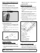
Figure 37. Rotor Direction of Rotation
REPLACING STUB SHAFT
1. Remove rotor (see Servicing Rotors (Flail Tubes),
page 30).
2. Remove three 1/2 x 2-1/2 hex bolts in taper lock
hub and re-install bolts in three threaded holes
(see Figure 38).
3. Tighten bolts evenly to release taper lock hub from
stub shaft. NOTE: You may have to give a sharp
blow directly to each bolt head to help the hub
disengage.
4. Unscrew stub shaft from the rotor tube.
5. Install new stub shaft, reversing Steps 1-3.
Figure 38. Stub Shaft Assembly
SERVICING WEASLER MODULAR
FRICTION CLUTCH
Tools Required
• 3/4" Socket wrench
• 8" Minimum C-clamps (2)
• 1/4" Hex Allen wrench
• Regular screwdriver or punch
• Duct tape or locking pliers with 3" throat minimum
•Hammer
• 1/2" sq. to 1" sq. bar x 9"
•Scale or Vernier
Breaking In the Clutch (Run In)
NOTE: All new clutches must be broken in (Run in) and
any clutch that has not been used for approximately 60
days.
1. Shut off tractor and disengage PTO.
2. Disconnect driveline from the tractor PTO shaft.
3. Loosen the bolts on the outside diameter of the
clutch until all bolts are just loose, then tighten all
bolts 1/2 turn.
4. Attach the driveline to the tractor PTO. Stand clear
of the unit.
5. Start tractor. Engage PTO clutch and run for a few
seconds or until clutch visibly smokes.
6. Disengage PTO. Shut off tractor. Disconnect
driveline from the tractor.
7. Tighten all bolts on the outside diameter of the
clutch until the compression plate is tight against
the housing.
8. Grease the fitting on the yoke, using a multi-
purpose high-temperature EP grease or an
equivalent lithium grease.
9. For an integral overrunning clutch, make sure
clutch turns freely in one direction.
Removing the Driveline
1. Shut off tractor and disengage PTO.
2. Disconnect driveline from PTO shaft.
3. Remove the bolt (21K) or clamp (24K) that
attaches the clutch to the shredder’s input shaft.