SS84-2 SS96-2 SS108-2 OPERATOR'S MANUAL ( 2/20/2012) MAN0884 SNOWBLOWER
TO THE DEALER: Assembly and proper installation of this product is the responsibility of the Woods® dealer. Read manual instructions and safety rules. Make sure all items on the Dealer’s Pre-Delivery and Delivery Check Lists in the Operator’s Manual are completed before releasing equipment to the owner. The dealer must complete the online Product Registration form at the Woods Dealer Website which certifies that all Dealer Check List items have been completed.
TABLE OF CONTENTS INTRODUCTION . . . . . . . . . . . . . . . . . . . . . . . . . . . . . . . . . . . . . . . . . . . . . . 2 SPECIFICATIONS . . . . . . . . . . . . . . . . . . . . . . . . . . . . . . . . . . . . . . . . . . . . . 4 GENERAL INFORMATION . . . . . . . . . . . . . . . . . . . . . . . . . . . . . . . . . . . . . . 4 SAFETY RULES . . . . . . . . . . . . . . . . . . . . . . . . . . . . . . . . . . . . . . . . . . . . . . 5 SAFETY DECALS . . . . . . . . . . . . . . . . . . . . . . . . . . . . . . .
SPECIFICATIONS Width Of Cut: . . . . . . . . . . . . . . . . . . SS84-2 . . . . . . . . . . . . . . . . . . . . . .84" SS96-2 . . . . . . . . . . . . . . . . . . . . . .96" SS108-2 . . . . . . . . . . . . . . . . . . . .108" Cutting Height . . . . . . . . . . . . . . . . . . . . . . . . . . . . . . . . . . . . . . . . . . . . . . .38" Number of Augers. . . . . . . . . . . . . . . . . . .1 (SS84-2), 2 (SS96-2 & SS108-2) Auger Diameter. . . . . . . . . . . . . . . . . . . . . . . . . . . . . . . . . . . . . .
SAFETY RULES ATTENTION! BECOME ALERT! YOUR SAFETY IS INVOLVED! Safety is a primary concern in the design and manufacture of our products. Unfortunately, our efforts to provide safe equipment can be wiped out by an operator’s single careless act. In addition to the design and configuration of equipment, hazard control and accident prevention are dependent upon the awareness, concern, judgement, and proper training of personnel involved in the operation, transport, maintenance and storage of equipment.
SAFETY RULES ATTENTION! BECOME ALERT! YOUR SAFETY IS INVOLVED! Do not operate or transport equipment while under the influence of alcohol or drugs. Operate only in daylight or good artificial light. Keep hands, feet, hair, and clothing away from equipment while engine is running. Stay clear of all moving parts. Always comply with all state and local lighting and marking requirements. Never allow riders on power unit or attachment.
installed securely to ensure equipment is in a safe condition before putting unit into service. ground, and system pressure is released by operating all valve control levers. Make sure all safety decals are installed. Replace if damaged. (See Safety Decals section for location.) Use a suitable lifting device of sufficient capacity. Use adequate personnel to handle heavy components. Make sure shields and guards are properly installed and in good condition. Replace if damaged.
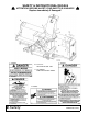
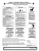
SAFETY & INSTRUCTIONAL DECALS ATTENTION! BECOME ALERT! YOUR SAFETY IS INVOLVED! Replace Immediately If Damaged! 3 - 1033602 5 - 1033270 10 - P/N 57123 REAR REFLECTOR - RED 11 - P/N 1002940 FRONT REFLECTOR - AMBER 1 - 1033600 4 - 1033603 8 Safety MAN0884 08/15/2011)
SAFETY & INSTRUCTIONAL DECALS ATTENTION! BECOME ALERT! YOUR SAFETY IS INVOLVED! Replace Immediately If Damaged! 9 - 1033274 8 - 1033273 6 - 1033271 7 - 1033272 2 - 1033601 2 - 55922 BE CAREFUL! Use a clean, damp cloth to clean safety decals. Avoid spraying too close to decals when using a pressure washer; high-pressure water can enter through very small scratches or under edges of decals causing them to peel or come off.
OPERATION The operator is responsible for the safe operation of the snowblower. The operator must be properly trained. Operators should be familiar with the tractor, snowblower, and all safety practices before starting operation. Read through safety rules and decals on page 5 through page 9. Safety instructions are important! Read all attachment and power unit manuals; follow all safety rules and safety decal information. (Replacement manuals and safety decals are available from your dealer.
The snowblower is mounted on a tractor 3-point hitch and driven by the tractor PTO. A centrally located gearbox directs power to the fan and auger. TRACTOR REQUIREMENTS 3-Point Hitch The SS snowblower requires the tractor to be equipped with a Category 2 or 3, three-point hitch. Hydraulic Circuit Either closed-center or open-center systems can be used for the hydraulic chute rotator and optional spout control.
dimension. If it is still less than 37.5", extend the hitch to mounting hole C. 7. Move the snowblower to the highest and lowest points of its operating range. Measure the distance between the lock groove on the tractor PTO shaft and the cross hole in the snowblower gearbox shaft at each point. The distance must not exceed 45.68". This dimension ensures a minimum of five inches of driveline telescoping engagement, which is required to prevent driveline failure and separation. 8.
Figure 3. Drive Halves Placed Parallel 4. Measure from end of upper shield to base of bell on the lower shield (A). Add 1-1/4" to dimension (A). Figure 6. Cut Shaft to Length 7. Repeat step 4 through 6 for other half of drive. 8. File and clean the cut ends of both drive halves. Ensure the drive halves slide smoothly together. Do not run tractor if proper driveline engagement cannot be obtained through these methods.
3. Before going to the work site, review "Transporting" section, page 15. 4. Position snowblower in a level area and lower into working position. 5. Starting Snowblower: ■ Be sure area is clear of all bystanders. ■ Run engine at low idle. ■ Slowly engage PTO control to start machine. ■ Slowly bring engine to rated PTO speed. Never exceed rated speed 6. Stopping Machine: ■ Slowly decrease engine speed to low idle.
NOTICE ■ Do not exceed 20 mph (32km/h). Reduce speed on rough roads and surfaces. When transporting snowblower, review and follow this procedure: ■ Be sure all bystanders are clear of machine. ■ Be sure that machine is securely attached to tractor and all retainer pins are installed. 5. Clevis Pin 8. Discharge Chute 9. Adjustment Strap Figure 8. Discharge Chute Position ■ Raise machine. ■ Do not allow riders. STORAGE WARNING ■ Keep bystanders away from equipment.
CLEANING After Each Use ■ Remove large debris such as clumps of dirt, grass, crop residue, etc. from machine. ■ Inspect machine and replace worn or damaged parts. ■ Replace any safety decals that are missing or not readable. Periodically or Before Extended Storage PRE-OPERATION CHECK LIST (OWNER'S RESPONSIBILITY) ___ Review and follow all safety rules and safety decal instructions on pages page 5 through page 9. ___ Check that all safety decals are installed and in good condition. Replace if damaged.
OWNER SERVICE The information in this section is written for operators who possess basic mechanical skills. Should you need help, your dealer has trained service technicians available. For your protection, read and follow all safety information in this manual. WARNING Safety instructions are important! Read all attachment and power unit manuals; follow all safety rules and safety decal information. (Replacement manuals and safety decals are available from your dealer.
4. Apply one pump of grease to each driveline u-joint grease fitting. 5. Apply one pump of grease to each of the plastic driveline shield bearings. 6. On the shear pin driveline, lubricate the shear yoke with grease to prevent galling. 7. Periodically check the yokes on the front PTO. Make sure the bolt and nut are tight and the yoke is not moving on the gearbox shaft. Driveline Shear Bolt Replacement PTO drivelines are equipped with shear bolts to protect against overloads.
Auger Drive Shear Bolt Replacement Gearbox ■ The gearbox is almost maintenance-free, but should be checked quarterly to be sure that the oil level is maintained at half full. A high quality gear oil with a viscosity index of 80W or 90W and an API service rating of GL-4 or -5 is recommended for use in the gearbox. Oil should be changed after the first 30 hours or 30 days of operating. Then, normal change should be adequate.
Skid Shoes PTO Driveline Guard The machine is equipped with skid shoes on the back side of housing under the hitch frame to prevent wearing the frame and provide depth control. They should be checked occasionally for wear and replaced if required. The shield must turn freely on PTO shaft. Daily lubrication of both shield bearings and periodic cleaning will ensure safe operation of the shield. If shield is damaged or worn, replace components with genuine Woods service parts.
TROUBLE SHOOTING PROBLEM PROBLEM CAUSES SUGGESTED SOLUTION PTO Shaft shear bolt continues to shear PTO shaft at too great an angle. Do not exceed a 15 degree angle at PTO shaft. PTO shear bolt is too soft. Use a grade 5 shear bolt. (GKN) Tilt on the snowblower is too great causing an excessive knuckle angle. Reduce tilt on snowblower by adjusting top link or upper 3point arm. Tractor ground speed is too fast. Reduce ground speed to allow augers to clear better. Insufficient fan speed.
ASSEMBLY INSTRUCTIONS DEALER SET-UP INSTRUCTIONS Assembly of this snowblower is the responsibility of the Woods dealer. It should be delivered to the owner completely assembled, lubricated and adjusted for normal conditions. The snowblower is shipped partially assembled. Assembly will be easier if components are aligned and loosely assembled before tightening hardware. Recommended torque values for hardware are located on page 33. Select a suitable working area.
2. Attach control box in tractor operator area. Attach end to a power source and ground on the tractor, (see tractors operator’s manual). 5. 14. 15. 16. Cable Tie Actuator 1/4 NC x 1-1/2 HHCS 1/4 NC Lock Nut Figure 18.
DEALER CHECK LISTS PRE-DELIVERY CHECK LIST (Dealer Responsibility) Inspect the equipment thoroughly after assembly to ensure it is set up properly before delivering it to the customer. The following check lists are a reminder of points to inspect. Check off each item as it is found satisfactory or after proper adjustment is made. ___ Check that all safety decals are installed and in good condition. Replace if damaged. ___ Check that shields and guards are properly installed and in good condition.
PARTS INDEX SS84-2, SS96-2 & SS108-2 SNOWBLOWER SS84-2, SS96-2 & SS108-2 ASSEMBLY . . . . . . . . . . . . . . . . . . . . . . . . 26 - 27 GEARBOX ASSEMBLY . . . . . . . . . . . . . . . . . . . . . . . . . . . . . . . . . . . . . . . . 28 DRIVE ASSEMBLY (BI-LOBE PROFILE). . . . . . . . . . . . . . . . . . . . . . . . . . . 29 DRIVE ASSEMBLY (STAR PROFILE) . . . . . . . . . . . . . . . . . . . . . . . . . . . . . 30 HYDRAULIC CHUTE DEFLECTOR (OPTIONAL) . . . . . . . . . . . . . . . . . . . .
SS84-2, SS96-2, SS108-2 SNOWBLOWER ASSEMBLY (MODEL SS96-2 SHOWN) 26 Parts MAN0884 (08/15/2011)
SS84-2, SS96-2, SS108-2 SNOWBLOWER PARTS LIST REF PART 1 NSS 2 1033225 3 1033720 4 1033717 5 1033723 6 1033646 7 12020143 7 12020057 7 12020227 8 12020013 9 103370084 9 103370096 9 1033700108 10 90101085 11 90101104 12 90101111 13 1033710 13 1033604 13 1033710 14 14 14 15 16 16 12030676 12030677 12030678 90311030 1033991 12030005 17 18 19 20 21 22 23 24 25 26 27 28 29 30 31 32 33 34 35 36 37 38 39 1033633 1033263 12030037 1033713 1033239 12030774 12030775 12030777 90405236 90519159 90519160 64332 12030
GEARBOX ASSEMBLY REF 1 2 3 5 6 8 12 13 14 PART 1033767 1033768 57478 1033770 1033771 1033772 603-1 1032448 438 QTY 2 2 2 1 1 1 1 1 1 DESCRIPTION Seal, Shaft 40 x 80 x 10 Snap Ring, Internal 80 x 2.5 Bearing, Tapered Roller Snap Ring, External 45 x 2.5 Cover Shim Kit, 65.3 Snap Ring, External 40 x 1.75 Bearing Tapered Roller Bearing, Ball (6207) 28 Parts REF 15 18 21 22 23 24 25 PART 57463 1007866 1007859 1033766 1033769 1033762 1033773 QTY 1 1 1 1 1 1 4 DESCRIPTION Seal, 35 x 72 x 10 Shim Kit, 35.
WALTERSCHEID BI-LOBE DRIVE ASSEMBLY SS84-2, SS96-2 & SS108-2 REF PART A ------B ------C ------1 38351 1 90317348 1 1029950 2 38352 3 90317916 4 40764 5 1034768 6 40588 7 38353 8 1029949 10 40766 13 40778 16 40777 17 1029932 18 1029947 19 1029948 20 40589 20 1003465 21 1005784 22 1033990 22 1034769 (Rev.
WALTERSCHEID STAR DRIVE ASSEMBLY SB30.84, SB40.96 & SB40.
HYDRAULIC CHUTE DEFLECTOR (OPTIONAL)) REF PART 1 1033300 2 66511 3 90501531 4 8572 5 11893 6 6698 * 7 920 * 8 21020219 HHCS * QTY 1 2 1 2 2 2 2 2 DESCRIPTION Hydraulic Cylinder 1 x 3 x 7.
ELECTRIC CHUTE DEFLECTOR (OPTIONAL) REF 5 14 15 16 PART 88 1033727 62788 * 6128 * HHCS * 32 Parts QTY 1 1 1 2 DESCRIPTION Plastic Tie (Ty-Rap) 3/16 x 14-1/4 Linear Actuator 1/4 NC x 1-1/2 HHCS GR5 1/4 NC Lock Nut Hex Head Cap Screw Standard Hardware, Obtain Locally MAN0884 (08/15/2011)
BOLT TORQUE CHART Always tighten hardware to these values unless a different torque value or tightening procedure is listed for a specific application. Fasteners must always be replaced with the same grade as specified in the manual parts list. Always use the proper tool for tightening hardware: SAE for SAE hardware and Metric for metric hardware. Make sure fastener threads are clean and you start thread engagement properly.
BOLT SIZE CHART NOTE: Chart shows bolt thread sizes and corresponding head (wrench) sizes for standard SAE and metric bolts. SAE Bolt Thread Sizes 5/16 3/8 1/2 IN MM 5/8 3/4 7/8 1 2 3 4 5 6 7 25 50 75 100 125 150 175 Metric Bolt Thread Sizes 8MM 10MM 12MM 14MM 16MM 18MM ABBREVIATIONS AG .............................................................. Agriculture ASABE ....................American Society of Agricultural & Biological Engineers (formerly ASAE) ASAE.......
WARRANTY All Models Except Mow’n MachineTM Zero-Turn Mowers Please Enter Information Below and Save for Future Reference. Date Purchased: ____________________________ From (Dealer): __________________________________________ Model Number: ____________________________ Serial Number: __________________________________________ Woods Equipment Company (“WOODS”) warrants this product to be free from defect in material and workmanship.
WARRANTY (Replacement Parts For All Models Except Mow’n MachineTM Zero-Turn Mowers) Woods Equipment Company (“WOODS”) warrants this product to be free from defect in material and workmanship for a period of ninety (90) days from the date of delivery of the product to the original purchaser with the exception of V-belts, which will be free of defect in material and workmanship for a period of 12 months.