on New Holland® Tractors T5040, T5050, T5060, T5070 2WD & FWA or Case IH® Tractors Farmall® 85U, Farmall 95U, Farmall 105U 2WD & FWA (1/16/2009) MAN0788 includes Hose Kits 58025, 1028835 HIS T E ! SAV NUAL MA e it with ual. an ud Incl ader M fety, r Lo ains sa epair u o y nt dr It co tion, an ation m r ra ope rt infor in othe pa und fo ls.
TO THE DEALER: Assembly and proper installation of this product is the responsibility of the Woods® dealer. Read manual instructions and safety rules. Make sure all items on the Dealer’s Pre-Delivery and Delivery Check Lists in the Loader Operator’s Manual are completed before releasing equipment to the owner. TO THE OWNER: Read this manual and Loader Operator’s Manual before operating your Woods equipment. The information presented will prepare you to do a better and safer job.
SAFETY RULES ATTENTION! BECOME ALERT! YOUR SAFETY IS INVOLVED! ! LEA EL INSTRUCTIVO! Si no lee Ingles, pida ayuda a alguien que si lo lea para que le traduzca las medidas de seguridad. Safety is a primary concern in the design and manufacture of our products. Unfortunately, our efforts to provide safe equipment can be wiped out by an operator’s single careless act.
LOADER MOUNT INSTALLATION WARNING ■ Only use this mounting kit for mounting Woods LUP126-2, LUP132-2 loaders on New Holland® T5040, T5050, T5060, T5070 2WD & FWA tractors and Case IH® Farmall® 85U, 95U and 105U 2WD & FWA tractors. Any other use or modification of this mounting kit may result in serious injury or death. Safety instructions are important! Read all attachment and power unit manuals; follow all safety rules and safety decal information.
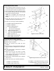
Install Right and Left Mid-Mounts NOTE: Use an overhead lifting device capable of lifting mount. Slide strap through loader mounting hole and cinch (Figure 1). Mount should be balanced and hang straight. 1. Attach right mount to loader ready bracket using four cap screws (12) and hardened washers (10). 2. Attach right mount (3) to the tractor frame using four cap screws (12) and hardened flat washers (10). 3. Repeat steps to install left mount (4).
Install Optional Grill Guard 1. Attach grill guard support bracket (A) to the front of the tractor using four cap screws (K), hardened flat washers (G), two spacers (C) and hex nuts (L) 2. Attach grill guard (B) to support bracket (A) using two (one per side) cap screw (E), four hardened flat washers (H) and hex nuts (D). NOTE: Do not overtighten cap screws (E); grill guard must be able to pivot for access to the battery. 3.
HOSE KIT INSTALLATION WARNING WARNING Keep hands and body away from pressurized lines. Use paper or cardboard, not hands or other body parts to check for leaks. Wear safety goggles. Hydraulic fluid under pressure can easily penetrate skin and will cause serious injury or death. Protective hose sleeves must cover all hydraulic hoses within 20 inches of the operator and be secured onto metal hose fittings.
1028835 Hose Kit Install Fittings and Hoses Install Hydraulic Fitting, Control Valve Install four adapters (4 or 5), elbows (8), colored bands (9-12), dust plugs (13) and female quick couplers (6) into the control valve located under the right tractor platform. See Figure 7. NOTE: Check thread pitch of the tractor valve ports and choose the correct adapter (4 or 5). Install Loader Hoses 1. Attach male quick couplers (7) and colored bands (9-12) to each of the loader feedline hoses (3). 2.
1028835 Hose Kit Secure Hoses Secure hoses to the back of right loader upright using plastic tie as shown in Figure 9. Do not cinch hoses tight, they need to move with the loader during operation. Figure 9. Secure Hoses Verify Control Movements 1. Mount loader to tractor: Remove mount pins from loader uprights. Align tractor with loader and slowly drive tractor into loader. Shut off tractor. 2. Connect loader feedline hoses to tractor control valve couplers following color shown in Figure 8. 3.
58025 HOSE KIT General Description These set-up instructions are for operating the LUP126-2 or LUP132-2 loader using the tractor hydraulic rear remote control couplers. To use this hydraulic connection, the tractor must be equipped with two hydraulic levers and four tractor hydraulic couplers shown in Figure 11. NOTE: Hydraulic couplers for connection to tractor are NOT INCLUDED with this hose kit but are available as service parts. Not all parts supplied in hose kit are used for this application.
58025 Hose Kit Install Hose Brackets 1. Remove right rear rockshaft housing cap screw and attach hose guide (5) as shown in Figure 13. Secure using tractor hardware. 2. Attach hose support (4) to right side of transmission housing using cap screw (6) and lock washer (7), Figure 14. 3. Tighten all cap screws to specifications given on the Bolt Torque Chart, Page 16. A D B C 4. Route hoses behind hose guide and connect hydraulic hoses to tractor hydraulic couplers as shown in Figure 13. 4. 5. 6. 7.
58025 Hose Kit Verification of Control Movements 1. Mount loader to tractor: Remove mount pins from loader uprights. Align tractor with loader and slowly drive tractor into loader. Shut off tractor. 2 1 2. Connect loader feedline hoses to tractor remote hydraulic couplers. See Figure 12. NOTE: At least 6" spacing should be maintained between valve, bracket, or hoses and any tractor control (brake pedals, accelerator, hand throttle, or hydraulic levers). 3.
2300012 LOADER MOUNTING KIT REF PART QTY DESCRIPTION REF 1 1026397 1 Left oscillation stop C 2 1026398 1 Right oscillation stop D 3 1028920 1 Right rear mount 4 1028921 1 Left rear mount 10 1006371 11 PART QTY 1028919 DESCRIPTION 2 Grill guard spacer 230 * 2 5/8 NC Hex nut E 902 * 2 5/8 NC x 2 HHCS GR5 F 26299 * 2 Clevis pin, 3/4 x 2 20 3/4 Hardened flat washer, extra thick G 57798 4 3/4 Hardened flat washer 1028950 4 M20 x 2.5P x 80 mm HHCS CL10.
1028835 HOSE KIT NOTE: Not all parts supplied with this hose kit are used for this application. REF PART QTY DESCRIPTION REF PART QTY DESCRIPTION 3 1009513 4 Hose, 76" x 3/8 NPTM x 3/4 JICM 9 395061 2 Plastic band, red 4 1010920 4 Adapter, M22 x 1.5M x 3/4 JICM 10 395062 2 Plastic band, blue 5 1012055 4 Adapter, M18 x 1.
58025 HOSE KIT REF PART QTY 1 53670 4 Hose 150" x 3/4 JICM x 3/4 JICM 2 313053 4 Elbow, 3/4 JICF x 1/2 NPTM 90° 3 66511 4 Quick coupler, male 1/2" (not included in kit) 4 54299 1 Hose support bracket 5 54305 1 Hose guide bracket 6 64084 1 M14 x 1.5P x 30 mm Cap screw 1 1/2 Lock washer 1 Tractor hardware 7 855 * 8 NS NOTE: Not all parts supplied with this hose kit are used for this application.
BOLT TORQUE CHART Always tighten hardware to these values unless a different torque value or tightening procedure is listed for a specific application. Fasteners must always be replaced with the same grade as specified in the manual parts list. Always use the proper tool for tightening hardware: SAE for SAE hardware and Metric for metric hardware. Make sure fastener threads are clean and you start thread engagement properly.
BOLT SIZE CHART NOTE: Chart shows bolt thread sizes and corresponding head (wrench) sizes for standard SAE and metric bolts. SAE Bolt Thread Sizes 5/16 3/8 1/2 IN MM 5/8 3/4 7/8 1 2 3 4 5 6 7 25 50 75 100 125 150 175 Metric Bolt Thread Sizes 8MM 10MM 12MM 14MM 16MM 18MM ABBREVIATIONS AG .............................................................. Agriculture ASABE.................... American Society of Agricultural & Biological Engineers (formerly ASAE) ASAE .......
WARRANTY (All Models Except Mow’n MachineTM Zero-Turn Mowers and Woods BoundaryTM Utility Vehicles) Please Enter Information Below and Save for Future Reference. Date Purchased: ____________________________ From (Dealer): __________________________________________ Model Number: ____________________________ Serial Number: __________________________________________ Woods Equipment Company (“WOODS”) warrants this product to be free from defect in material and workmanship.
WARRANTY (Replacement Parts For All Models Except Mow’n MachineTM Zero-Turn Mowers and Woods BoundaryTM Utility Vehicles) Woods Equipment Company (“WOODS”) warrants this product to be free from defect in material and workmanship for a period of ninety (90) days from the date of delivery of the product to the original purchaser with the exception of V-belts, which will be free of defect in material and workmanship for a period of 12 months.
Woods Equipment Company 2606 South Illinois Route 2 Post Office Box 1000 Oregon, Illinois 61061 USA 800-319-6637 tel 800-399-6637 fax www.WoodsEquipment.com ©2009 Woods Equipment Company. All rights reserved. WOODS and the Woods logo are trademarks of Woods Equipment Company. All other trademarks, trade names, or service marks not owned by Woods Equipment Company that appear in this manual are the property of their respective companies or mark holders. Specifications subject to change without notice.