PRD6000 PRD7200 PRD8400 (Rev. 6/22/2007) MAN0475 2-FRONT Tested. Proven. Unbeatable.
TO THE DEALER: Assembly and proper installation of this product is the responsibility of the Woods® dealer. Read manual instructions and safety rules. Make sure all items on the Dealer’s Pre-Delivery and Delivery Check Lists in the Operator’s Manual are completed before releasing equipment to the owner. The dealer must complete the Product Registration included with the Operator’s Manual. The customer must sign the registration which certifies that all Dealer Check List items have been completed.
TABLE OF CONTENTS INTRODUCTION . . . . . . . . . . . . . . . . . . . . . . . . . . . . . . . . . . . . . . . . . . . . . . 2 SPECIFICATIONS. . . . . . . . . . . . . . . . . . . . . . . . . . . . . . . . . . . . . . . . . . . . . 4 GENERAL INFORMATION . . . . . . . . . . . . . . . . . . . . . . . . . . . . . . . . . . . . . . 4 SAFETY RULES . . . . . . . . . . . . . . . . . . . . . . . . . . . . . . . . . . . . . . . . . . . . . 5-7 SAFETY DECALS . . . . . . . . . . . . . . . . . . . . . . . . . . . . . . .
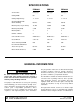
SPECIFICATIONS PRD6000 PRD7200 PRD8400 3-Point Hitch Category 1 Category 1 Category 1 Cutting Width 60" 72" 84" Cutting Height Range 1" - 5-1/2" 1" - 5-1/2" 1" - 4-1/4" Operating Weight with Chain Shielding 653 lbs 719 lbs 830 lbs Blade Speed (feet per minute) 18,100 18,000 17,900 Blade Speed (RPM) 3,295 2,748 2,329 Blade Spindles 3 3 3 Number of Blades 3 3 3 Universal Drive Series ASAE Cat. 3 ASAE Cat. 3 ASAE Cat. 3 Caster Wheels 3.25 x 10 3.25 x 10 4.
SAFETY RULES ATTENTION! BECOME ALERT! YOUR SAFETY IS INVOLVED! Safety is a primary concern in the design and manufacture of our products. Unfortunately, our efforts to provide safe equipment can be wiped out by an operator’s single careless act. In addition to the design and configuration of equipment, hazard control and accident prevention are dependent upon the awareness, concern, judgement, and proper training of personnel involved in the operation, transport, maintenance and storage of equipment.
SAFETY RULES ATTENTION! BECOME ALERT! YOUR SAFETY IS INVOLVED! (Safety Rules continued from previous page) Keep bystanders away from equipment. Do not operate or transport equipment while under the influence of alcohol or drugs. Operate only in daylight or good artificial light. Keep hands, feet, hair, and clothing away from equipment while engine is running. Stay clear of all moving parts. Always comply with all state and local lighting and marking requirements.
SAFETY RULES ATTENTION! BECOME ALERT! YOUR SAFETY IS INVOLVED! Tighten all bolts, nuts, and screws to torque chart specifications. Check that all cotter pins are installed securely to ensure equipment is in a safe condition before putting unit into service. Use care when installing or removing belt from spring-loaded idler. Springs store energy when extended and, if released suddenly, can cause personal injury. Make sure all safety decals are installed. Replace if damaged.
SAFETY & INSTRUCTIONAL DECALS ATTENTION! BECOME ALERT! YOUR SAFETY IS INVOLVED! Replace Immediately If Damaged! DANGER DANGER 1 - 15503 SHIELD MISSING DO NOT OPERATE PUT SHIELD ON 2 - 18867 18867--B ROTATING BLADES AND THROWN OBJECTS Do not put hands or feet under or into mower when MODEL NO. SERIAL NO. engine is running. Before mowing, clear area of objects that may be Woods Equipment Company Oregon, Illinois, U.S.A. thrown by blade. Keep bystanders away.
SAFETY & INSTRUCTIONAL DECALS ATTENTION! BECOME ALERT! YOUR SAFETY IS INVOLVED! Replace Immediately If Damaged! WARNING WARNING DO NOT EXCEED PTO SPEED OF 540 RPM PTO speeds higher than 540 RPM can cause equipment failure and personal injury. 18866-D FALLING OFF CAN RESULT IN BEING RUN OVER. Tractor must be equipped with ROPS (or ROPS CAB) and seat 4 - 18866 belt. Keep foldable ROPS systems in “locked up” position at all times. Buckle Up! Keep seat belt securely fastened.
OPERATION The operator is responsible for the safe operation of the mower. The operator must be properly trained. Operators should be familiar with the mower, the tractor, and all safety practices before starting operation. Read the safety rules and safety decals on 5 to 9. This mower is designed for lawn and grass mowing. It is not designed for rough conditions or heavy weed mowing. It is equipped with suction type blades for best results in lawn mowing.
1. Attach the mower hitch pins to the lower tractor lift arms and secure. 2. Attach tractor top link (1), Figure 2, to mower top link bracket attachment point A. Connect the driveline to the tractor PTO shaft. CUTTING HEIGHT ADJUSTMENT WARNING Keep all persons away from operator control area while performing adjustments, service, or maintenance. IMPORTANT ■ Avoid low cutting heights. Striking the ground with blades produces one of the most damaging shock loads a mower can encounter.
SPACERS REQUIRED UNDER CASTER ARM PIVOT TUBE Cut Height 1/2" Spacer 3/4" Spacer 1" Space r 1-1/4" *Spacer (Spring) The mower has three lower hitch plate attachment points (D), Figure 6. It may be necessary to change the mower hitch plate attachment point to obtain proper tire clearance and/or lift height. 1" 1-1/2" 1 2" 1 2-1/2" 1 1 3" 2 3-1/2" 4" 1 * 4-1/4" 4-1/2" * 5" * 5-1/2" * 1 1 1 1 2 1 1 1 1 1 2 1 1 2 1 1 1. Tractor top link A. Mower top link attachment point B.
Figure 8. Front Caster Arm Configuration for PRD6000 & PRD7200 Only FRONT CASTER WHEEL INTERFERENCE CHECK IMPORTANT ■ Do not operate tractor and mower until this interference check has been performed. If you change tractors, you must perform the check for that mounting. 2. Pivot both front caster wheels forward and check that there is clearance between caster wheels and tractor tires. 3. If there is interference on models PRD6000 and PRD7200, mount front casters in the outer position.
If mower becomes plugged causing belt to slip for over two seconds follow these steps: 1. Maneuver equipment into a previously cut area and allow mower to clear accumulated material. 2. Continue running at least two minutes, allowing pulleys to cool. Stopping the mower in contact with a very hot pulley will bake and ruin belt. Uneven Terrain WARNING Do not operate or transport on steep slopes. Do not stop, start, or change directions suddenly on slopes.
OWNER PRE-OPERATION CHECK LIST (OWNER'S RESPONSIBILITY) ___ Review and follow all safety rules and safety decal instructions on pages 5 to 9. ___ Check that all safety decals are installed and in good condition. Replace if damaged. ___ Check that all shields and guards are properly installed and in good condition. Replace if damaged. ___ Check that chain shielding is in good condition and replace any damaged chain links. ___ Check that all hardware and cotter pins are properly installed and secured.
OWNER SERVICE The information in this section is written for operators who possess basic mechanical skills. If you need help, your dealer has trained service technicians available. For your protection, read and follow the safety information in this manual. WARNING Never allow children or untrained persons to operate equipment. Keep bystanders away from equipment.
REF DESCRIPTION FREQUENCY 1 Front U-Joint 8 Hours 2 Caster Wheel (Four wheels) 8 Hours 3 Caster Pivot (Four wheels) 8 Hours 4 Left Spindle (Access through hole) 24 Hours 5 Shield Bearings 8 Hours 6 Rear U-Joint 8 Hours 7 Gearbox (Fill to center of horizontal shaft with SAE 90W gear lube) Check Daily 8 Right Spindle (Access through hole) 24 Hours 9 Center Spindle (Access through hole) 24 Hours 10 Slip Joints 8 Hours Figure 12.
Figure 13. Belt Routing BELT SERVICE Belt Replacement One of the major causes of belt failure is improper installation. Before installing a new belt, check the following: 1. Check pulley shafts and bearings for wear. 2. Check pulley grooves for cleanliness. 3. Make sure spindles turn freely and without wobble. If grooves require cleaning, moisten a cloth with a nonflammable, non-toxic degreasing agent or commercial detergent and water. 5.
Blade Installation 1. Remove blades. CAUTION Your dealer can supply genuine replacement blades. Substitute blades may not meet original equipment specifications and may be dangerous. 2. Always sharpen both ends at the same time to maintain balance. 3. Follow original sharpening pattern. 4. Do not sharpen blade to a razor edge. Leave from 1/32" to 1/16" blunt edge. 5. Do not sharpen back side. CHAIN SHIELDING DANGER 1. Spindle assembly 2. Blade 3. 1/2 NC x 1-1/2 HHCS GR5 4.
TROUBLE SHOOTING MOWING CONDITIONS PROBLEM Grass cut higher in center of swath than at edge Grass cut lower in center of swath than at edge Streaking conditions in swath Material discharges from mower unevenly; bunches of material along swath POSSIBLE CAUSE SOLUTION Height of mower higher at front than at rear Adjust mower height and attitude so that mower rear and front are within 1/2 inch of same height. See instructions on page 11. Loose blade Check blade hardware.
TROUBLE SHOOTING BELT CONDITIONS PROBLEM Belt slippage POSSIBLE CAUSE SOLUTION Mower overloading; Material too tall or heavy Reduce tractor ground speed but maintain full PTO rpm. Cut material twice, one high pass and then mow at desired height. Cut at 90 degrees to first pass. Oil on belt from over lubrication Be careful not to overlubricate. Clean lubricant from belt and pulleys with clean rag. Replace oil-soaked belt. Belt hung up or rubbing Check belt position in pulleys and idlers.
DEALER SERVICE The information in this section is written for dealer service personnel. The repair described here requires special skills and tools. If your shop is not properly equipped or your mechanics are not properly trained in this type of repair, you may be time and money ahead to replace complete assemblies. WARNING Before working underneath, read manual instructions, securely block up, and check stability.
Spindle Assembly Refer to Figure 17. Bearing cones and cups are designed to work together. It is important to position them so bearing cone taper mates with cup taper. 1. Lubricate new cups with a light oil. Place them in spindle housing so they will mate with bearing cones. Cups and cones are a press fit to minimize wear. Seat cups securely with a press or place a large drift in the flat lip and drive them into housing until cup seats against machined shoulder of housing.
. 1. 2. 3. 4. 5. 6. 7. 8. 9. 10. 11. 12. 13. 14. 15. 16. 17. 18. 19. Crown gear Gearbox housing Input shaft Output shaft Gear pinion Bearing Bearing Protective flat washer Cotter pin Snap ring Snap ring Spacer Shim Castle nut Castle nut M24 x 2 Shim Flat washer Oil seal (40 x 80 x 12 mm) Oil seal (35 x 72 x 10 mm) 20. 21. 22. 23. 24. 25. 26. 27. Cap Snap ring Top cover Bolt M8 x 14 mm Breather level plug Cotter pin Bearing Ball bearing Figure 18.
with an OD that will sit on the outside edge of the seal but will clear the housing. Tubing with an OD that is too small will bow seal cage and ruin seal. 5. Carefully press seal into housing, avoiding distortion to the metal seal cage. 1. 2. 3. 4. Gearbox Removal from Mower Refer to Figure 20. Seal Pipe or tube Seal seat Casting Pipe or tube must press at outer edge of Incorrect Installation 1. 2. 3. 4. 5. Figure 19. Seal Installation Vertical Shaft Seal Replacement 1.
Gearbox Disassembly Refer to Figure 18. 1. Remove top cover (22) from housing. Turn gearbox upside down and pour out remaining gear oil from gearbox. 2. Remove oil cap (20) (to be replaced). 1. Clean housing, paying specific attention to areas where gaskets will be installed. 2. Wash housing and all components thoroughly. Select a clean area for gearbox assembly. Replace all seals, bearings, and gaskets. All parts must be clean and lightly oiled before reassembling. 3.
19. Check gearbox housing for leaks by plugging all holes except one. Apply 4 psi compressed air and immerse the gearbox in water to verify that there are no leaks. UNIVERSAL JOINT REPAIR 1. 2. 3. 4. 20. Remove gearbox from water and dry off with compressed air. Add SAE 80W or 90W EP oil until it runs out of side level hole. Tighten all plugs. Yoke Cup and bearings Snap ring Journal cross Gearbox Installation NOTE: Gearbox is heavy: do not attempt to move without mechanical assistance. 1.
3. Clamp cup in vise as shown in Figure 25 and tap on yoke to completely remove cup from yoke. Repeat Step 2 and Step 3 for opposite cup. final removal. Drive remaining cup out with a drift and hammer. U-Joint Assembly 1. Place seals securely on bearing cups. Insert cup into yoke from outside and press in with hand pressure as far as possible. Insert journal cross into bearing cup with grease fitting away from shaft. Be careful not to disturb needle bearings.
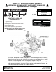
ASSEMBLY INSTRUCTIONS DEALER SET-UP INSTRUCTIONS Assembly of this mower is the responsibility of the Woods dealer. If should be delivered to the owner completely assembled, lubricated, and adjusted for normal cutting conditions. Complete Dealer Check Lists on page 33 when you have completed the assembly. The mower is shipped partially assembled. Assembly will be easier if components are aligned and loosely assembled before tightening hardware. Recommended torque values for hardware are located on page 45.
Install Top Link 2. Repeat for opposite side. 3. Tighten bolts so that caster arm is snug against deck bracket, but not fully torqued. 44 40 11 9 NOTE: Refer to Front Caster Wheel Interference Check, page 13 for possible front caster arm positions. 4. Attach front caster arm in desired position and tighten snug against deck bracket. 30 Torque Caster Arm Hardware 10 CM757 CM757 1. Lift mower off shipping pallet and set on a hard level surface.
Fill Gearbox 2. Secure with carriage bolts (14) and flanged lock nuts (15). IMPORTANT ■ Gearbox is not filled at the factory. Prior to delivery, make sure each gearbox is filled half-full with 80W or 90W API GL-4 or GL-5 gear lube. 1. Make sure vent plug hole is clear. Fill gearbox halffull with high quality gear oil that has a viscosity index of 80W or 90W and an API service rating of GL-4 or GL-5. 2. Fill gearbox until oil runs out the side plug on gearbox. 3.
CHAIN CUT-TO-LENGTH CHART Model Dimension “A” PRD6000 40" PRD7200 45" PRD8400 50" NOTE: This kit is used on other models. Use only the hardware listed below. 1. 2. 3. 4. 5. 6. Offset link, .38 x 2 x 15" Chain, 3/8 proof coil 38-link Sleeve, .94 x 1.44 x 1.94" Screw, 1/2 NC x 6 HHCS GR5 Washer, 1/2" flat Sleeve, .50 x .75 x 3.38" 7. 8. 9. 10. 11. 12. Nut, 1/2 NC flange lock Sleeve, 7/8 x 1-1/8 x 19/32" HT Washer, 3/4 flat Sleeve, .81 x 1.25 x 1.
DEALER CHECK LISTS PRE-DELIVERY CHECK LIST (DEALER’S RESPONSIBILITY) Inspect the equipment thoroughly after assembly to ensure it is set up properly before delivering it to the customer. The following check lists are a reminder of points to inspect. Check off each item as it is found satisfactory or after proper adjustment is made. ___ Check that all safety decals are installed and in good condition. Replace if damaged. ___ Check that shields and guards are properly installed and in good condition.
NOTES 34 Notes MAN0475 (9/21/2005)
PARTS INDEX Premier Rear Discharge Mowers: PRD6000 PRD7200 PRD8400 MAIN FRAME ASSEMBLY . . . . . . . . . . . . . . . . . . . . . . . . . . . . . . . 36 - 37 GEARBOX ASSEMBLY . . . . . . . . . . . . . . . . . . . . . . . . . . . . . . . . . . . . . 38 DRIVESHAFT ASSEMBLY (WALTERSCHEID TWO-LOBE) . . . . . . . . 39 DRIVESHAFT ASSEMBLY (COMER PROFILE) . . . . . . . . . . . . . . . . . . . . BLADE & SPINDLE ASSEMBLY . . . . . . . . . . . . . . . . . . . . . . . . . . . . . . 41 REAR CHAIN SHIELDING ASSEMBLY .
PRD6000, PRD7200 & PRD8400 MAIN FRAME ASSEMBLY 36 Parts (Rev.
PRD6000, PRD7200 & PRD8400 MAIN FRAME ASSEMBLY REF PART QTY 1 2 3 4 4 4 5 –––– 1016501 20409 1001244 18879 53418 18989 1 2 2 1 1 1 4 5 5 1016511 19754 4 4 6 7 65577 34466 8 4 7 8 19756 29368 4 4 8 9 9 9 10 11 12 19749 55331 19578 52873 19579 19605 33647 4 2 12 13 52854 65129 4 4 13 14 52853 65130 4 8 14 15 16 17 18 19 52855 8 67407 4 33677 4 855 * 4 6100 * 6 67318 4 19 19747 4 19 52859 4 20 20 21 22 23 24 25 25 25 1014401 1014403 12296 * 1014416 51849 53534 1014417 1014418 52
PRD6000, PRD7200 & PRD8400 GEARBOX ASSEMBLY REF PART QTY DESCRIPTION A 1002499 1 57458 2 NSS 3 1005320 1 Shaft, Input 1-3/8 -6 4 1005321 1 Shaft, Output 1-1/4 5 57491 1 Pinion Gear 13T M5.3 6 57476 1 Bearing Cup & Cone 7 57462 1 Bearing Cup & Cone 8 20888 1 Washer, 1.58 x 3.13 x .04 Protective Flat 9 1 Gearbox Assembly, Complete 1 Gear, Crown 25T M5.
PRD6000, PRD7200 & PRD8400 DRIVESHAFT WALTERSCHEID (TWO-LOBE SHAFT) REF PART QTY DESCRIPTION REF PART QTY DESCRIPTION A 40551 1 Complete Drive Shaft 14 40778 1 Screw, Guard Retainer (Pkg of 10) 1 40571 2 Yoke, 1-3/8 6-Spline QD 17 40779 1 Grease Zerk, Drive Line (Pkg of 10) 2 154 2 U-Joint Repair Kit L14R 18 40780 1 Bearing, Guard Support 3 40775 1 Pin, Spring 10 mm x 65 mm (Pkg of 10) 20 40589 2 Slide Lock Collar Repair Kit (without yoke) 4 40572 1 Yoke, Inner Pro
PRD6000, PRD7200 & PRD8400 DRIVESHAFT COMER REF PART QTY DESCRIPTION A 1009508 1 Complete driveline asy 1 1001300 2 Complete collar yoke C12 1-3/8 - 6 2 38478 2 Cross and bearing kit 3 1019442 1 Outer cone fix ring 4 30922 6 Protection fixing screw 5 1019444 1 Inner cone fix ring 40 Parts REF PART QTY DESCRIPTION 6 30917 2 Chain-shield tether 9 1001340 1 Lock collar repair kit 10 1001302 1 Flexible pin 11 1001301 1 Outer yoke tube 12 1001305 1 Flexible pi
PRD6000, PRD7200 & PRD8400 BLADE & SPINDLE ASSEMBLY REF PART DESCRIPTION 1 37009 2 10378 * Screw, HHCS 1/4 NC x 1 GR5 3 52898 4 Nut, Jam 7/8 NF Washer, Lock .929 x 1.66 1985 * Washer, Lock 1/4 5 34440 Bushing, H 1 Straight bore w/key 6 66694 Sheave, H 1 BK 4.17 PD (PRD6000) -or- 6 12622 Sheave, H 1 BK 5.0 PD (PRD7200) -or- 6 53419 Sheave, H 1 BK 5.9 PD (PRD8400) 7 52881 Spindle Assembly, Complete 8 52949 Seal, 1.50 x 2.12 x .31 9 52872 Sleeve, 1.14 x 1.50 x .
PRD6000, PRD7200 & PRD8400 REAR CHAIN SHIELDING ASSEMBLY (OPTIONAL) REF PART QTY DESCRIPTION A 55348 - Chain Shield Assembly (PRD6000) B 53566 - Chain Shield Assembly (PRD7200) C 52856 - Chain Shield Assembly (PRD8400) 1 1007854 1 Pin, Chain (for PRD6000 only) -or- 1 1007856 1 Pin, Chain (for PRD7200 only) -or- 1 1007850 2 Pin, Chain (for PRD8400 only) 2 4763 - Chain, 3 Link, 1/4 Proof (use 54 for PRD6000; 66 for PRD7200; 78 for PRD8400) CD4997A REF PART QTY DESCRIPTION
MULCHING KIT (OPTIONAL) 1 x x x x 2 NOTE: Use high lift blades for best performance if tractor does not have enough horsepower for the high lift blades, then use low lift blades. REF PART QTY DESCRIPTION A 1019430 1 PRD6000 Mulching kit A 1019431 1 PRD7200 Mulching kit A 1019432 1 PRD8400 Mulching kit 1 6100 * - 1/2 x 1-1/4 Cap screw GR5 2 11900 * - 1/2 Flanged lock nut * Obtain Locally INSTALLATION INSTRUCTIONS 1.
QUICK HITCH KIT (OPTIONAL) CHAIN CUT-TO-LENGTH CHART Model Dimension “A” PRD6000 40" PRD7200 45" PRD8400 50" NOTE: This kit is used on other models. Use only the hardware listed below. REF PART QTY 1 1003692 2 Link, Offset .38 x 2.0 x 15 2 1005401 2 Chain, 3/8 Proof Coil 38-Link 3 1016517 2 Sleeve, .94 x 1.44 x 1.94" 4 13563 1 Screw, 1/2 NC x 6 HHCS GR5 5 854 6 Washer, 1/2" Flat 6 29368 1 Sleeve, .50 x .75 x 3.
SKID SHOE KIT (OPTIONAL) MOWER DECK DIMENSION “A” PRD6000 7.25" PRD7200 9.50" PRD8400 12.25" REF PART QTY DESCRIPTION A 1004111 1 Skid Shoe Kit (contains 1 left and 1 right skid shoe) 1 1004105 1 Skid Shoe, Left 2 1004106 1 Skid Shoe, Right 3 6100 * - Screw, 1/2 NC x 1-1/4 HHCS GR5 4 11900 * - Nut, 1/2 NC Flange Lock * Obtain Locally INSTALLATION INSTRUCTIONS 1. Locate and drill three 17/32" holes using the dimensions from the drawing and table above. 2.
BOLT TORQUE CHART Always tighten hardware to these values unless a different torque value or tightening procedure is listed for a specific application. Fasteners must always be replaced with the same grade as specified in the manual parts list. Always use the proper tool for tightening hardware: SAE for SAE hardware and Metric for metric hardware. Make sure fastener threads are clean and you start thread engagement properly.
BOLT SIZE CHART NOTE: Chart shows bolt thread sizes and corresponding head (wrench) sizes for standard SAE and metric bolts. SAE Bolt Thread Sizes 5/16 3/8 1/2 IN MM 5/8 3/4 7/8 1 2 3 4 5 6 7 25 50 75 100 125 150 175 Metric Bolt Thread Sizes 8MM 10MM 12MM 14MM 16MM 18MM ABBREVIATIONS AG ............................................................. Agriculture ATF...............................Automatic Transmission Fluid BSPP ..........................
INDEX ASSEMBLY Dealer Set-Up Instructions 29 Initial Oil Fill 31 Optional Equipment Chain Shielding 31 Front Roller 31 Quick Hitch Kit 31 Skid Shoe Kit 43, 45 DEALER CHECK LISTS Delivery (Dealer’s Responsibility) 33 Pre-Delivery (Dealer’s Responsibility) 33 DEALER SERVICE Blade Spindle Assembly 23 Disassembly 22 Installation 23 Removal 22 Service 22 Blocking Method 22 Gearbox Disassembly 26 Drive Sheave Installation 27 Horizontal Shaft Seal Replacement 25 Installation 27 Reassembly 26 Removal 25 Repair 24 S
WARRANTY (All Models Except Mow’n Machine TM Zero-Turn Mowers and Woods BoundaryTM Utility Vehicles) Please Enter Information Below and Save for Future Reference. Date Purchased: ____________________________ From (Dealer): ___________________________________________ Model Number: ____________________________ Serial Number: ___________________________________________ Woods Equipment Company (“WOODS”) warrants this product to be free from defect in material and workmanship.
WARRANTY (Replacement Parts For All Models Except Mow’n MachineTM Zero-Turn Mowers and Woods BoundaryTM Utility Vehicles) Woods Equipment Company (“WOODS”) warrants this product to be free from defect in material and workmanship for a period of ninety (90) days from the date of delivery of the product to the original purchaser with the exception of V-belts, which will be free of defect in material and workmanship for a period of 12 months.