
Operator`s manual


Operation 17
MAN0500 (3/24/2006)
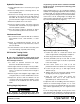
When shredding attitude is set, check that the distance
from the bottom rear edge of the wing to the ground
matches the bottom edge of the rear center section to
the ground. With the cutting height and attitude estab-
lished, adjust the driveline carrier bearing in the H-
frame to ensure the front driveline is parallel to the
ground.
STORAGE
Follow these steps when storing your cutter:
1. Clean cutter before storing. See page 23 for
cleaning instructions. Store on level, solid ground.
2. Disconnect driveline and secure up off the ground.
3. Lower wings to ground.
4. Raise cutter center section and pin transport bar in
raised position.
5. Attach parking jack and raise tongue weight off
tractor drawbar.
6. Place wedge blocks at front and rear of wheels on
center section and each wing to prevent wheel
rotation.
7. Securely block all four corners of center section
and each wing with jackstands.
8. Remove hydraulic hoses after tractor is turned off
and all system pressure is released by operating
valve levers several times. Store hoses on hose
holder.
9. Remove safety tow chain.
10. Remove retainer pin and high strength drawbar
pin.
11. Keep children and bystanders away from storage
area.
TRANSPORTING
Power unit must be equipped with ROPS or
ROPS cab and seat belt. Keep seat belt securely
fastened. Falling off power unit can result in death
from being run over or crushed. Keep foldable
ROPS system in “locked up” position at all times.
Always raise unit and install transport locks
before transporting. Leak down or failure of
mechanical or hydraulic system can cause equip-
ment to drop.
Always attach safety chain to tractor drawbar
when transporting unit.
Never exceed 20 mph during transport.
Never allow riders on power unit or attachment.
Do not operate PTO during transport.
Do not operate or transport on steep slopes.
Do not operate or transport equipment while
under the influence of alcohol or drugs.
Always comply with all state and local lighting
and marking requirements.
Lock-Up
Always transport with wings and center frame in the
raised, locked position.
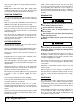
Wing Lock-Up
1. Raise wing to the UP position.
2. Remove lock-up pin from storage position.
3. Place lock-up pin in lock position and secure with
safety pin.
4. Repeat steps 1 to 3 for opposite wing.
5. Lower cylinder against lock-up bars (Figure 3).
Figure 3. Transport Lock-Up, Left Wing
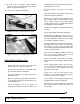
Center Section Lock-up
1. Raise cutter with hydraulic cylinder to maximum
height.
2. Rotate transport lock into position over cylinder rod
(Figure 4).
3. Lower cutter against transport lock.
CAUTION