
Operator`s manual


Owner Service 21
MAN0500 (3/24/2006)
Seasonal Lubrication
In addition to the daily recommended lubrication, a
more extensive application is recommended season-
ally or before a new unit is placed into service.
1. Fill CV double yokes with 20 pumps of grease with
the joints in a straight line.
2. Articulate CV body to maximum angle several
times to ensure full coverage of joints.
3. Place joints in the straight position and add 10
additional pumps of grease to both joints.
4. Wipe telescoping drive clean of all old grease and
contaminants.
5. Add a thin layer of new grease over telescoping
drive.
BLADE SERVICE
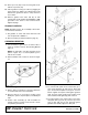
Before working underneath, read manual
instructions, securely block up, and check stability.
Secure blocking prevents equipment from drop-
ping due to hydraulic leak down, hydraulic system
failure, or mechanical component failure.
Blade Removal
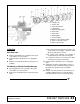
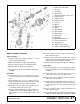
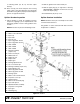
Figure 7. Blade Assembly
IMPORTANT
■ If blade pin is seized in crossbar and extreme
force will be needed to remove it, support crossbar
from below to prevent gearbox damage.
1. Disconnect driveline from tractor PTO.
2. Raise cutter and block securely (see Figure 6).
3. Open blade access cover and align crossbar
assembly (10) with blade access hole in the cutter
frame. Remove cap screw (53), blade pin lock clip
(14), keyhole plate (13), and shims (11 & 12).
Carefully drive blade pin (9) out of crossbar.
4. Rotate crossbar and repeat for opposite blade.
Blade Installation
Your dealer can supply genuine replacement
blades. Substitute blades may not meet original
equipment specifications and may be dangerous.
IMPORTANT
■ Crossbar rotation has clockwise rotation on left
gearbox and counterclockwise rotation on the right
and center gearboxes when looking down on cut-
ter. Be sure to install blade cutting edge to lead in
correct rotation.
NOTE: Always replace or sharpen both blades at the
same time.
1. Inspect blade pin (9) for nicks or gouges, and if you
find any replace the blade pin.
2. Insert blade pin through the blade. Blade should
swivel on blade pin; if it doesn’t, determine the
cause and correct.
3. Align crossbar assembly (10) with blade access
hole in cutter frame. Apply a liberal coating of
Never-Seez
®
or equivalent to blade pin and
crossbar hole. Make sure blade offset is down
away from cutter.
4. Insert blade pin through blade. Push blade pin
through crossbar.
5. Install shims (11 & 12) over blade pin.
NOTE: Only use enough shims to allow keyhole
plate (13) to slide into blade pin groove.
6. Install blade clip (14) over keyhole plate and into
blade pin groove.
7. Secure into position with cap screw (53). Torque
cap screw to 85 lbs-ft.
8. Repeat steps for opposite side.
9. Blade pin
10. Crossbar assembly
11. Shim, 18 ga
12. Shim, 20 ga
13. Keyhole plate
14. Blade lock clip
53. 1/2 NC x 1-1/4 HHCS GR5