
Operator`s manual


Assembly 33
MAN0500 (3/24/2006)
ASSEMBLY INSTRUCTIONS
DEALER SET-UP INSTRUCTIONS
Assembly of this cutter is the responsibility of the
WOODS dealer. It should be delivered to the owner
completely assembled, lubricated and adjusted for nor-
mal cutting conditions.
The cutter is shipped partially assembled. Assembly
will be easier if components are aligned and loosely
assembled before tightening hardware. Recommended
torque values for hardware are located on page 76.
Select a suitable working area. A smooth hard surface,
such as concrete, will make assembly much quicker.
Open parts boxes and lay out parts and hardware to
make location easy. Refer to illustrations, accompany-
ing text, parts lists and exploded view drawings.
Complete the check list on page 45 when assembly is
complete and cutter is delivered to the customer.
Before working underneath, carefully read Oper-
ator’s Manual instructions, disconnect driveline,
raise mower, securely block up all corners with
jackstands, and check stability. Secure blocking
prevents equipment from dropping due to hydrau-
lic leak down, hydraulic system failures, or
mechanical component failures.
Do not disconnect hydraulic lines until machine
is securely blocked or placed in lowest position
and system pressure is released by operating
valve levers.
Always wear relatively tight and belted clothing
to avoid getting caught in moving parts. Wear
sturdy, rough-soled work shoes and protective
equipment for eyes, hair, hands, hearing, and head;
and respirator or filter mask where appropriate.
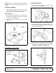
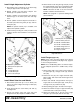
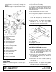
Install Center Wheel Yoke Arm
NOTE: Install center rear chain shield or rubber belting
before installing wheel yoke arm. This will make instal-
lation of shielding much easier.
Attach wheel yoke arm (7) to center section using three
1-1/4 pivot pins (4), carriage bolts (58), and flange lock
nuts (50).
Figure 22. Center Wheel Yoke Arm Installation
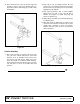
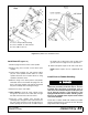
Install Attitude Rod
1. Insert each attitude rod (6) through center deck
channels and through pivot castings in wheel yoke
arm assembly. The rod is a very tight fit; use care
to prevent thread damage during installation.
2. Loosely install spacer (43), washer (56) and two
nuts (57) on end of each attitude rod.
Figure 23. Attitude Rod Installation
CAUTION
4. 1-1/4 Pivot pin
7. Center wheel yoke arm
50. 1/2 NC Flange lock nut
58. 1/2 NC x 1-1/2 Carriage bolt GR5
6. Attitude rod
43. Spacer, 1 x 3-3/4
56. 1" Flat washer
57. 1" NC Hex nut