
Operator`s manual


Assembly 37
MAN0500 (3/24/2006)
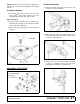
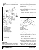
Figure 29. Wing Cylinder Installation
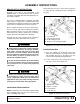
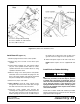
Install Wing Wheel Yoke Arm (Figure 30)
1. Attach wheel yoke arm (6) to wing section using
two pivot pins (30), carriage screws (37), and hex
nuts (40).
2. Repeat procedure for opposite wing. (Note:
BW1260 has only the right wing installed.
BW1260L has only the left wing installed.)
NOTE: See page 40 for optional walking beam
wheel yoke.
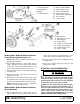
Install Wing Wheel and Hub (Figure 30)
1. Insert wheel hub into outside of wheel yoke arm (6)
and align holes.
2. Secure into position using cap screw (39) and
flanged lock nut (40).
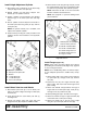
3. Attach wheel to hub using five lug nuts (61). Install
the chamfered side of the lug nut toward the inside
for steel rim for pneumatic tires and rims (shown).
NOTE: Install the flat side of the nut toward the
inside for solid tires and aircraft tires.
4. Install optional dual wheel and hub to inside of
wheel yoke arm.
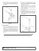
Figure 30. Wing Wheel Yoke Arm & Hub Installation
4. Hydraulic cylinder
16. Cylinder link
17. Cylinder link
31. Clevis pin, 1 x 2.26
32. Clevis pin, 1 x 3-5/8
36. Cotter pin, 1/4 x 1-1/2
52. 1" Flat washer
6. Wing solid wheel yoke arm
30. Wing pivot pin
37. 1/2 NC x 1-1/2 Carriage bolt GR5
40. 1/2 NC Flange lock nut
6. Wing solid wheel yoke arm
39. 1/2 NC x 3 HHCS GR5
40. 1/2 NC Flange Lock nut
61. Lug nut, 1/2 NF
(Rev. 7/10/2006)