
Operator`s manual


Assembly 39
MAN0500 (3/24/2006)
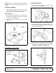
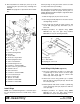
Figure 34. Cylinder Hose Installation, Rear
Install Hose Kit (Figure 34)
1. Remove plug from base end of center cylinder.
2. Remove plug from rod end of each wheel yoke
cylinder.
3. Install reducer bushing (21) and restricter elbow
(22) into each cylinder. Position elbow on center
cylinder toward the front. Position elbows on wing
cylinders toward the center.
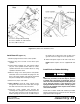
4. With the wings in the down position and cylinder
extended, remove and reinstall the plugs from the
base of the wing cylinders. This will trap air behind
the piston and help when lowering the wings.
5. Attach hose (23) to each elbow.
6. Hose Routing: Feed the wing cylinder hoses
through the rear holes in the center deck, through
the deck channels and out the front frame.
7. Feed the center cylinder hose through the
remaining hole, through the deck channels and out
the front frame. Insert the hoses through the hose
holder opening, be sure the hose can slide freely in
the holder. Do not allow hose slack to drag on the
ground or become caught on tractor protrusions.
8. Attach male quick coupler to the end of each hose.
NOTE: Quick couplers are not supplied with this
unit.
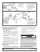
Install Chain or Rubber Shielding
Full chain or rubber shielding, designed to
reduce the possibility of thrown objects, must be
installed when operating in populated areas or
other areas where thrown objects could injure peo-
ple or damage property. If this machine is not
equipped with full chain or rubber shielding, opera-
tion must be stopped when anyone comes within
several hundred feet.
Install chain or rubber shields with hardware provided.
Note that flat washers are used over all slots. See parts
pages 66 and 68 for diagrams.
21. 1/2 x 1/4 Pipe reducer bushing
22. 1/4 x 1/4 Elbow, w/ 1/16 restricter
23. Hose, 200" x 1/4 x 1/4
(Rev. 7/10/2006)