ALUMA-CLASSIC™ FENCE W1716 & W1720 INSTRUCTION MANUAL Phone: 1-360-734-3482 • On-Line Technical Support: tech-support@shopfox.biz COPYRIGHT © APRIL, 2004 BY WOODSTOCK INTERNATIONAL, INC. REVISED JANUARY, 2008 (BL) WARNING: NO PORTION OF THIS MANUAL MAY BE REPRODUCED IN ANY SHAPE OR FORM WITHOUT THE WRITTEN APPROVAL OF WOODSTOCK INTERNATIONAL, INC.
INTRODUCTION 2 INTRODUCTION ASSEMBLY 4 SAFETY ADJUSTMENTS 9 Contents About-Your-New-Aluma-Classic™-Fence Woodstock-Service-and-Support Unpacking Get-To-Know-Your-Fence Location-of-Controls 2 2 3 3 3 Inventory W1716-Installation W1720-Installation Installing-Metal-Extension-Wings PARTS 9 10 11 ASSEMBLY Fence-to-Blade Scale-Installation-And-Adjustment 4 5 6 8 ADJUSTMENTS OPERATIONS MAINTENANCE PARTS USE THE QUICK GUIDE PAGE LABELS TO SEARCH OUT INFORMATION FAST!
INTRODUCTION INTRODUCTION About Your New Aluma-Classic™ Fence Your new SHOP FOX® Model W1716/W1720 Aluma-Classic™ Fence is specially designed to provide many years of trouble-free service. Close attention to engineering detail, ruggedly built parts, and a rigid quality control program assure safe and reliable operation. The Aluma-Classic™ Fence features an extruded aluminum and steel construction, utilizing a sturdy Tshape design that fits most table saws easily.
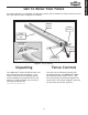
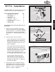
For proper operation it is important to know your machine and its components. Please take the time to learn the features shown in Figure 1 & 1a below. Fence Body Scale Indicator Height Adjustment Bolt Parallel Setscrews Locking Lever Leveling Setscrews Figure 1a. Figure 1. Fence features. Unpacking Fence Controls The SHOP FOX® W1716/W1720 has been carefully packaged for safe transporting.
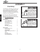
ASSEMBLY Inventory ASSEMBLY The following is a description of the main components shipped with the SHOP FOX® Model W1716/W1720 Aluma-Classic™ Fence. You should lay the components out to easily identify them. The inventory for the Models W1721 and W1722 are also listed below. READ and understand this entire instruction manual before performing any operations with your machine. Serious personal injury may occur if safety and operational information is not understood and followed.
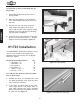
W1716 Installation /16"-18 x 1" Cap Screws 5 The SHOP FOX® W1716 Aluma-Classic™ Fence comes in a box with its own hardware bag. Qty 4 8 6 8 6 4 1 1 Figure 2. Rear fence rail bracket. To install the fence rail to the table saw, do these steps: 1. Install the rear rail bracket (long angle iron) to the back side of the table (Figure 2), with the four 5⁄16" cap screws. The holes in the extension wings are not threaded and require 5⁄16" nuts and washers to secure them. 2.
ASSEMBLY To install the rip fence to the table saw, do these steps: 1. Thread the handle knob onto the fence locking handle. 2. Make sure the handle is in the unlocked “UP” position before placing the fence on the rails. 3. Check to see that the fence clears the table surface throughout its range of travel, and increase or decrease the height between the fence and table by adjusting the bolt shown in Figure 5. 4. Adjustment Bolt Figure 5. Adjustment bolt.
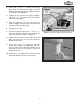
3. Insert two 5⁄16"-18 x 3⁄4" T-bolts in the right table wing, and two into the edge of the left table wing, and install the flat washers and nuts on each bolt. See Figure 8. 4. Tighten all nuts until there is a gap of approximately 3⁄16" to 1⁄4" between the T-bolt and the table and wing edges. 5. Slide the extension rail over the T-bolts as shown in Figure 1 until the rail is flush with the end edge of the left table wing. 6. Tighten all hex nuts. 7.
Installing Metal Extension Wings The SHOP FOX® Heavy-Duty Metal Extension Wings (Figure 10) can be installed on the Model W1720 79" rails. ASSEMBLY Hardware Bag Contents: • Flat Washer 5⁄16" • T-Bolt 5⁄16" -18 x 1" • Hex Nut 5⁄16"-18 Qty 12 12 12 Figure 10. Extension wing box inventory. To install the W1720 extension wings, do these steps: 1. Loosely install the T-bolts, washers and hex nuts into the short sides of the extension wings. 2.
ADJUSTMENTS The SHOP FOX® W1716/W1720 Aluma-Classic™ Fence requires little adjustment since most of the features are built in at the factory. The primary adjustment is to position the fence so it is parallel to the saw blade. DISCONNECT power to the saw at this time! Otherwise, serious injury may occur. Fence Parallelism If your table saw has been properly adjusted, the saw blade should be parallel to the miter slot.
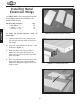
Scale Installation & Adjustment The self-adhesive scale provides fast and accurate fence positioning. It is best to install the scale after all other adjustments in this section have been made. Figure 15 shows the scale properly installed on the front rail. To install the scale indicator, do these steps: 1. UNPLUG THE TABLE SAW! Figure 15. Scale installed on front rail. 2. Raise the blade to its maximum height. ADJUSTMENTS 3. Position the fence against the right side of the blade. 4.
W1716 SHOP FOX® Aluma-Classic™ Fence 5 4 1 3 24 17 5 5 12 16 23 37 19 18 39 6 22 7 25 3 8 15 37 20 21 9 26 5 14 32 38 36 29 30 29 23 33 34 35 PARTS -11-
W1716 SHOP FOX® Aluma-Classic™ Fence PART # 1 3 4 5 6 7 8 9 12 14 15 16 17 18 19 20 21 22 23 24 25 26 29 30 32 33 34 35 36 37 38 39 X1716001 X1716003 X1716004 X1716005 X1716006 X1716007 X1716008 X1716009 X1716012 X1716014 XPSS05 XPW03 XPS06 XPB25 PB88 XPLN02 XPLN01 XPS24 XPN02 X1716024 X1716025 X1716026 XPW07 X1716030 X1716032 XPFH25 X1716033 XPB05 X1716036 XPSS05 XPSB03 X1716039 DESCRIPTION FENCE BODY ASSEMBLY FENCE SIDEBOARD FENCE PLUG FENCE SIDEBOARD CAP ADJUSTMENT BOLT 5⁄16"-18 CLAMP HANDLE FEMALE K
W1720 SHOP FOX® Aluma-Classic™ Fence 5 4 1 3 24 17 5 5 12 16 23 22 37 19 18 7 39 6 25 3 8 15 37 20 21 9 26 5 14 131 201 134 202 103 203 204 131 114 113 141 123 121 141 111 113 124 140 102 123 113 141 134 131 127 115 113 141 131 124 122 -13- 118 PARTS 126
W1720 SHOP FOX® Aluma-Classic™ Fence PART # 1 3 4 5 6 7 8 9 12 14 15 16 17 18 19 20 21 22 24 25 26 37 X1716001 X1716003 X1716004 X1716005 X1716006 X1716007 X1716008 X1716009 X1716012 X1716014 XPSS05 XPW03 XPS06 XPB25 XPB119 XPLN02 XPLN01 XPS24 X1716024 X1716025 X1716026 XPSS05 DESCRIPTION FENCE BODY ASSEMBLY FENCE SIDEBOARD FENCE PLUG FENCE SIDEBOARD CAP ADJUSTMENT BOLT 5⁄16"-18 CLAMP HANDLE FEMALE KNOB CLEAR INDICATOR SLIDER 19 X 50 X 2T SETSCREW 5⁄16"-18 X 1⁄4" FLAT WASHER #10 PHLP HD SCR 10-24 X 3⁄8"
WARRANTY CARD Name___________________________________________________________________________________________ Street___________________________________________________________________________________________ City _______________________________________________________________State________Zip______________ Phone Number_______________________E-Mail_______________________FAX_____________________________ MODEL #___________________________________ Serial # ____________________________________ The following infor
FOLD ALONG DOTTED LINE Place Stamp Here WOODSTOCK INTERNATIONAL, INC. P.O.