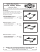
Mobile Base Models D2057A, D2058A, D2260A Instruction Sheet Phone #: (360) 734-3482 • Online Tech Support: tech-support@shopfox.biz • Web: www.shopfox.biz Introduction Your new Mobile Base is designed to give you a stable and mobile platform upon which to mount machinery and equipment. Be sure to select the model that matches your machine specifications. D2057A Specifications (see Figure 1) • • • Minimum Inside Dimensions..................... 20" x 20" Maximum Inside Dimensions..............
D2057A, D2058A, D2260A Mobile Base Instructions Available Accessories Base modification accessories are available for machines with an extension table or machine bases larger than the maximum inside dimensions of Model D2058A. D2259A—Mobile Base Extension Kit Model D2259A (see Figure 4) is designed to install onto the Model D2260A or D2057A mobile base to provide a stable support platform for a machine and an extension table unit. Specifications • • • Minimum Extension Length.........................
D2057A, D2058A, D2260A Mobile Base Instructions Tools Needed for Assembly Tape Measure.....................................................1 Wrenches or Sockets 13mm....................................2 Light Machine Oil (Optional)....................... As Needed Crowbar (Optional)..............................................1 Rubber Mallet (Optional).......................................1 6" 2x4's (Optional)...............................................2 6" 2x6 (Optional)..............................
D2057A, D2058A, D2260A Mobile Base Instructions Preparation for Assembly There is more than one way to assemble the mobile base. Each method has advantages and disadvantages, depending on the size and weight of the machine that you plan to put on the mobile base. The purpose of this section is to help you decide which method will work best for your situation.
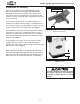
D2057A, D2058A, D2260A Mobile Base Instructions Assembling Base & Mounting Machine 1. Mount the two swivel casters to the corner brackets with threaded posts(see Figure 9), using (4) M8-1.25 x 16 hex bolts, 8mm flat washers, 8mm lock washers, and M8-1.25 hex nuts on each. x4 Threaded Post Figure 9. Swivel caster mounted to corner bracket with threaded post. 2. Mount the two fixed casters to the remaining brackets (see Figure 10), using (4) M8-1.
D2057A, D2058A, D2260A Mobile Base Instructions 4. Position the swivel casters on the "front" or side from which the machine will typically be pushed (see Figure 12). Fixed Casters Note: Wipe a light coat of machine oil onto the top, bottom, and sides of the rail ends before the next step to make it easier to slide the rails into the brackets and simplify later adjustments. Swivel Casters "Front" Figure 12. Corner brackets with casters laid out on floor. 5.
D2057A, D2058A, D2260A Mobile Base Instructions 7. Thread (1) 8mm lock nut halfway onto each M8-1.25 X 25 hex bolt with the nylon insert on the nut facing the head of the bolt. 8. Secure each end of the rails to the corner brackets with (2) M8-1.25 x 25 hex bolt and 8mm lock nut assemblies as shown in Figure 15. Tighten the lock nuts against the rail. Each side rail-to-corner bracket connection must use both hex bolts, making a total of four bolts at each corner, as shown in Figure 15.
D2057A, D2058A, D2260A Mobile Base Instructions Assembling Base Around Machine 1. Thread a knob several turns into each foot post, as shown in Figure 17. 2. Insert a foot into the bottom of each foot post (see Figure 17). The magnetized knob shaft should pick up the foot when it comes in close proximity. Knob Foot Post Foot Figure 17. Installing foot and knob into a foot post. 3.
D2057A, D2058A, D2260A Mobile Base Instructions 7. Slide the other ends of the rails into the corner brackets from Step 6. Secure each end of the rails to the corner brackets with (2) M8-1.25 x 25 hex bolt and 8mm lock nut assemblies (see Figure 20). 8. Tighten lock nuts against the rails. 9. While an assistant lifts one side of the machine up, slide the front rail-bracket assembly from Step 7 under the machine, as shown in Figure 21. x2 x2 Figure 20. Rails fastened to brackets.
D2057A, D2058A, D2260A Mobile Base Instructions 11. With the help of an assistant, lift the rear side of the machine up, then place a 4x4 block under the machine. 12. Slide each of the corner brackets onto the remaining rail, slide the assembly into the rails, over the block and up against the machine, as shown in Figure 24. 12" 4x4 Figure 24. Fixed casters and rail placed around back of machine, which is raised up with a wood block. 13. Secure each end of the rails to the corner brackets with (2) M8-1.
D2057A, D2058A, D2260A Mobile Base Instructions 19. While an assistant lifts up on the back of the machine, slide the rear fixed caster assembly onto the side rails of the front rail-corner bracket assembly so the rear assembly is close to the machine base, and the corner pads slide under the machine, as shown in Figure 27.
D2057A, D2058A, D2260A Mobile Base Instructions Making a Base Plate If the footprint of the machine is too small for the mobile base or the machine doors or fixtures do not clear the side rails, you can mount it to a base plate, as shown in Figure 30. OR A good quality base plate can increase the standard footprint of machines, such as drill presses, to make them more stable.
D2057A, D2058A, D2260A Mobile Base Instructions Using Mobile Base 1. DISCONNECT THE MACHINE FROM POWER! 2. With the machine mounted on the mobile base, turn the knobs on the corner brackets counterclockwise so the feet clear the floor by at least 1⁄8". Lift heavy equipment carefully and with the proper equipment. Get assistance if needed to reduce the risk of serious personal injury. — If the floor is uneven, retract the feet completely to eliminate the chance of the pads dragging on the floor. 3.
D2057A, D2058A, D2260A Mobile Base Instructions D2057A Parts 15 5 REAR RIGHT 6 7 7 5 5 10 3 6 6 3 11 17 14 3 2 5 or 9 6 12 13 3 1 7 LEFT 18 18 1 16 FRONT 8 REF PART # DESCRIPTION REF PART # DESCRIPTION 1 2 3 5 6 7 8 9 10 SWIVEL CASTER FIXED CASTER RAIL 21-1/4" LONG HEX BOLT M8-1.25 X 25 LOCK NUT M8-1.25 SHOP FOX LOGO LABEL FOOT WITH MAGNET KNOB M12-1.75 HEX BOLT M8-1.25 X 16 11 12 13 14 15 16 17 18 FLAT WASHER 8MM LOCK WASHER 8MM HEX NUT M8-1.
D2057A, D2058A, D2260A Mobile Base Instructions D2058A Parts 15 5 REAR RIGHT 6 7 7 5 5 10 3 6 6 4 11 17 14 4 2 5 or 3 9 6 1 12 13 LEFT 18 18 1 16 7 FRONT 8 REF PART # DESCRIPTION REF PART # DESCRIPTION 1 2 3 4 5 6 7 8 9 SWIVEL CASTER FIXED CASTER RAIL 20" LONG RAIL 25" LONG HEX BOLT M8-1.25 X 25 LOCK NUT M8-1.25 SHOP FOX LOGO LABEL FOOT WITH MAGNET KNOB M12-1.75 10 11 12 13 14 15 16 17 18 HEX BOLT M8-1.25 X 16 FLAT WASHER 8MM LOCK WASHER 8MM HEX NUT M8-1.
D2057A, D2058A, D2260A Mobile Base Instructions D2260A Parts 15 5 REAR RIGHT 6 7 7 5 5 10 3 6 6 4 11 17 14 4 2 5 or 3 9 6 1 12 13 7 LEFT 18 18 1 16 FRONT 8 REF PART # DESCRIPTION REF PART # DESCRIPTION 1 2 3 4 5 6 7 8 9 SWIVEL CASTER FIXED CASTER RAIL 10-5/8" LONG RAIL 15-1/8" LONG HEX BOLT M8-1.25 X 16 LOCK NUT M8-1.25 SHOP FOX LOGO LABEL FOOT WITH MAGNET KNOB M12-1.75 10 11 12 13 14 15 16 17 18 HEX BOLT M8-1.25 X 16 FLAT WASHER 8MM LOCK WASHER 8MM HEX NUT M8-1.