MODEL M1001 6" X 26" VERTICAL MILL INSTRUCTION MANUAL Phone: (360) 734-3482 • On-Line Technical Support: tech-support@shopfox.biz COPYRIGHT © JANUARY, 2005 BY WOODSTOCK INTERNATIONAL, INC., REVISED JANUARY, 2015 (ST) #6799PC WARNING: NO PORTION OF THIS MANUAL MAY BE REPRODUCED IN ANY SHAPE OR FORM WITHOUT THE WRITTEN APPROVAL OF WOODSTOCK INTERNATIONAL, INC.
This manual provides critical safety instructions on the proper setup, operation, maintenance, and service of this machine/tool. Save this document, refer to it often, and use it to instruct other operators. Failure to read, understand and follow the instructions in this manual may result in fire or serious personal injury—including amputation, electrocution, or death. The owner of this machine/tool is solely responsible for its safe use.
SAFETY................................................7 Standard Machinery Safety Instructions....... 7 Additional Safety Instructions for Vertical Mills................................................. 9 WARRANTY......................................... 40 Warranty Registration.......................... 41 OPERATIONS MAINTENANCE OPERATIONS....................................... 18 General........................................... 18 Positioning Spindle Head....................... 18 Table Travel.......
INTRODUCTION M1001 6" x 26" Vertical Mill INTRODUCTION Woodstock Technical Support We stand behind our machines! In the event that questions arise about your machine, parts are missing, or a defect is found, please contact Woodstock International Technical Support at (360) 734-3482 or send e-mail to: tech-support@shopfox.biz. Our knowledgeable staff will help you troubleshoot problems and send out parts for warranty claims.
INTRODUCTION M1001 6" x 26" Vertical Mill MODEL M1001 SHOP FOX® VERTICAL MILL 6" X 26" Motors Main Type......................................................................... TEFC Capacitor Start Induction Horsepower........................................................................................... 1-1/2 HP Voltage.............................................................................................. 110V/220V Prewired.....................................................................
INTRODUCTION M1001 6" x 26" Vertical Mill Table Info Table Length.............................................................................................. 26 in. Table Width........................................................................................... 6-1/8 in. Table Thickness....................................................................................... 1-3/4 in. Number of T-Slots.............................................................................................
Electrical Power Requirement............................................................. 110V/220V, Single-Phase, 60 Hz Prewired Voltage................................................................................................. 110V Minimum Circuit Size................................................................... 20A at 110V, 15A at 220V Switch................................................................................................. ON/OFF Switch Switch Voltage...........................
INTRODUCTION M1001 6" x 26" Vertical Mill Controls and Features E D F C G B A N H O M I L J K A. B. C. D. E. F. G. H. I. J. K. L. M. N. O.
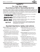
M1001 6" x 26" Vertical Mill SAFETY The purpose of safety symbols is to attract your attention to possible hazardous conditions. This manual uses a series of symbols and signal words intended to convey the level of importance of the safety messages. The progression of symbols is described below.
SAFETY M1001 6" x 26" Vertical Mill APPROVED OPERATION. Untrained operators can be seriously hurt by machinery. Only allow trained or properly supervised people to use machine. When machine is not being used, disconnect power, remove switch keys, or lock-out machine to prevent unauthorized use—especially around children. Make workshop kid proof! STABLE MACHINE. Unexpected movement during operations greatly increases the risk of injury and loss of control.
M1001 6" x 26" Vertical Mill Additional Safety Instructions for Vertical Mills USE this and other machinery with caution and respect. Always consider safety first, as it applies to your individual working conditions. No list of safety guidelines can be complete—every shop environment is different. Failure to follow guidelines could result in serious personal injury, damage to equipment or poor work results. MILL ASSEMBLY. Do not operate until unit is assembled and installed according to instructions.
M1001 6" x 26" Vertical Mill ELECTRICAL ELECTRICAL Availability Before installing the machine, consider the availability and proximity of the required power supply circuit. If an existing circuit does not meet the requirements for this machine, a new circuit must be installed. To minimize the risk of electrocution, fire, or equipment damage, installation work and electrical wiring must be done by a qualified electrician in accordance with all applicable codes and standards.
M1001 6" x 26" Vertical Mill Circuit Information A power supply circuit includes all electrical equipment between the breaker box or fuse panel in the building and the machine. The power supply circuit used for this machine must be sized to safely handle the fullload current drawn from the machine for an extended period of time. (If this machine is connected to a circuit protected by fuses, use a time delay fuse marked D.
M1001 6" x 26" Vertical Mill Grounding & Plug Requirements This machine MUST be grounded. In the event of certain malfunctions or breakdowns, grounding reduces the risk of electric shock by providing a path of least resistance for electric current. ELECTRICAL For 110V operation: This machine is equipped with a power cord that has an equipment-grounding wire and a grounding plug (similar to the figure on the right).
M1001 6" x 26" Vertical Mill SETUP Unpacking The SHOP FOX® Model M1001 has been carefully packaged for safe transporting. If you notice the machine has been damaged, please contact your authorized SHOP FOX® dealer immediately. Inventory The following is a description of the main components shipped with the SHOP FOX® Model M1001. Lay the components out to inventory them. Wooden Box Contents (Figures 3 & 4) Qty A. Milling Machine.............................................1 B. Toolbox......................
M1001 6" x 26" Vertical Mill SET UP Machine Placement • Floor Load: Your vertical mill has a large weight load of 822 lbs. in a small footprint. We recommend placing this mill on a concrete floor. • Working Clearances: Consider existing and anticipated needs, size of material to be processed through the machine, and space for auxiliary stands, work tables or other machinery when establishing a location for your vertical mill (see Figure 5).
M1001 6" x 26" Vertical Mill Mounting Mill on Shop Floor Although not required, it is recommend that you mount your new mill to the floor. Because this is an optional step and floor materials may vary, floor mounting hardware is not included. Generally, you can either bolt your machine to the floor or mount it on machine mounts. Both options are described below. Whichever option you choose, it will be necessary to use a precision level to level your mill (see Figures 6-8).
M1001 6" x 26" Vertical Mill Assembly The Model M1001 comes fully assembled from the factory with the exception of one of the longitudinal handwheels and the cross handwheel. The head has been rotated to reduce the overall dimension of the shipping crate. Nuts 2 & 3 Hidden from View Headstock Adjustment Loosen the three nuts at the column and rotate the headstock to the "0" position on the column scale (see Figure 10).
M1001 6" x 26" Vertical Mill Spindle Controls Figure 13 shows the location of the ON/OFF buttons and the SPINDLE DIRECTION toggle for the Model M1001. • The ON/OFF buttons control power to the spindle. • The SPINDLE DIRECTION toggle will change the direction the spindle rotates.
M1001 6" x 26" Vertical Mill OPERATIONS General The Model M1001 will perform many types of operations that are beyond the scope of this manual. Many of these operations can be dangerous or deadly if performed incorrectly. The instructions in this section are written with the understanding that the operator has the necessary knowledge and skills to operate this machine.
M1001 6" x 26" Vertical Mill To rotate the spindle head horizontally, do these steps: 1. UNPLUG THE MILL! 2. Make sure the spindle is stopped and the work area is free from obstructions before proceeding. 3. Using a 17mm wrench, loosen the three locking nuts shown in Figure 14. 4. Push or pull the spindle head to swivel it to the desired position. Use the scale located on the column to set the angle desired. 5. Tighten the three nuts to lock the headstock in position.
M1001 6" x 26" Vertical Mill Graduated Dials The table handwheels and the knee handle have graduated dials. Each mark represents 0.001" of movement and one full revolution equals 0.100" The graduated dials float and can be indexed or "zeroed" by loosening the knurled head thumb screw, rotating the graduated dial to "0", and securing the setting with the knurled head thumb screw (see Figure 17). Example: Suppose you want to drill a series of holes with 1/2" centers (0.500").
M1001 6" x 26" Vertical Mill Quill Travel Quill Feed Control Pinch Bolt The quill feed is controlled by the quill feed handle shown in Figure 20. The handle allows the mill to operate as a drill. To use the quill feed handle, do these steps: 1. 2. Pull the quill feed handle (see Figure 20) forward to feed the quill down towards the workpiece. The quill feed handle is spring loaded to assist in returning the handle to the upmost vertical position.
M1001 6" x 26" Vertical Mill Determining Needed RPM Before changing speeds, you must first determine the best RPM to use with the material and diameter of your cutting tool. Using this determined RPM, you can then set the mill to match that speed. Workpiece Material Cutting Speed (SFM) Aluminum & Alloys 300 To determine the RPM needed for your workpiece, do these steps: Brass & Bronze 150 Copper 100 1.
M1001 6" x 26" Vertical Mill Setting RPM Setting the RPM on the Model M1001 involves placing the V-belts on the pulleys as shown in the spindle speed chart below. Motor Release Lever To set the spindle speed, do these steps: 1. Examine the Spindle Speed Chart in Figure 24 to find the closest match to your needed RPM. 2. UNPLUG THE MILL! 3. Open the pulley cover. 4. Loosen the motor release lever and move the motor toward the spindle to loosen the tension on the V-belts. 5.
M1001 6" x 26" Vertical Mill Spindle Break-in Procedure Complete this process once you have familiarized yourself with all instructions in this manual and have made sure the machine is completely lubricated. NOTICE The spindle break-in procedure is important for ensuring long life and trouble-free performance from your mill. Failure to perform this proceedure can shorten the life of your machine and void your warranty. OPERATIONS To break-in the spindle, do these steps: 1.
M1001 6" x 26" Vertical Mill Installing Tools To load a tool in the spindle, do these steps: 1. UNPLUG THE MILL! 2. Turn the mill OFF, allow it to come to a complete stop and unplug the mill. 3. Clean any debris from the spindle opening. 4. Insert the tool holder or a collet into the spindle. 5. Rotate the holder until the groove lines up with the key and the holder slides into the spindle. 6. Use a wrench to tighten the drawbar (see Figure 26) until the tool is secure in the spindle.
M1001 6" x 26" Vertical Mill MAINTENANCE General Regular periodic maintenance on your SHOP FOX® mill will ensure optimum performance. Make a habit of inspecting your mill each time you use it. Check for the following conditions and repair or replace when necessary: • • • • • • • Loose chucks and arbors. Loose vices or clamps. Loose mounting bolts. Worn switch and safety shut off features. Worn or damaged cords and plugs. Damaged V-belt.
M1001 6" x 26" Vertical Mill Lubrication Power Feed The power feed uses SAE 40 oil and should not need to be changed unless the unit is being repaired. Knee Screw Single Shot Lubrication System Use the single shot lubrication system to oil the ways, the crossfeed screw, and the longitudinal screw by pumping the handle on the reservoir 2-4 times each day (see Figure 27). Fill the reservoir regularly with ISO 68 or SAE 20 weight machine oil. Figure 27. Single shot lubrication system.
M1001 6" x 26" Vertical Mill Maintenance Schedule Daily: • Pump handle of the one shot lubrication system 2-4 times. • Clean machine to remove debris. • Make sure table/vise is clean and free of metal chips. • Clean spindle openings before inserting tools. • Check for any unsafe conditions. Weekly: • Place five drops of oil on the drawbar splines. • Thoroughly clean the machine ways to remove chips and debris. • Clean and grease the longitudinal, cross, and knee lead screws.
M1001 6" x 26" Vertical Mill SERVICE General This section covers the most common service adjustments or procedures that may need to be made during the life of your machine. Always disconnect your machine from the power source before performing any service! If you require additional machine service not included in this section, please contact Woodstock International Technical Support at (360) 734-3482 or send e-mail to: tech-support@shopfox.biz. Figure 29. Cross gib screw.
M1001 6" x 26" Vertical Mill Adjusting Backlash Backlash is the amount of play found in a leadscrew. It can be found by turning the cross slide handwheel in one direction, and then turning the handwheel the other direction. When the cross slide begins to move, the backlash has been taken up. Adjustment Cap Screws Leadscrews are adjusted for backlash at the factory and should not need any adjustment for many hours of machine use, if ever.
M1001 6" x 26" Vertical Mill Electrical Safety Instructions These pages are current at the time of printing. However, in the spirit of improvement, we may make changes to the electrical systems of future machines. Study this diagram carefully. If you notice differences between your machine and these wiring diagrams, call Woodstock International Technical Support at (360) 734-3482. 1. 2. 3. 4. SHOCK HAZARD. Working on wiring that is connected to a power source is extremely dangerous.
M1001 6" x 26" Vertical Mill Electrical Parts Identification DZ47LE C32 Contactor Read Page 31 STOP DZ47 Contactor Before Wiring Move wire to position A for 220V operation. A Transformer Terminal Bar Wiring Box SERVICE Figure 34. M1001 Electrical panel.
M1001 6" x 26" Vertical Mill Wiring Diagram 265 VAC 150�F Capacitor Contactor 110V (230V) 110V (230V) 2A Starter U1 Reverse Switch Z2 24V,40W V2 Z1 Motor 400 VAC 20 ±5 �F Capacitor Figure 37. M1001 Wiring schematic. Figure 35. Motor wiring box currently wired for 110V. Read Page 31 STOP Jumpers Red Black Before Wiring Red Black 110V wiring for motor Red Jumpers Black Black Red 230V wiring for motor SERVICE Figure 36. Motor wiring for 110V or 230V. Also refer to Figure 37.
M1001 6" x 26" Vertical Mill Troubleshooting This section covers the most common problems. WARNING! DO NOT make any adjustments until the mill is unplugged and all moving parts have come to a complete stop. SYMPTOM POSSIBLE CAUSE CORRECTIVE ACTION Motor will not start. 1. Tripped circuit breaker or relay inside machine wiring box or power source breaker box. 2. Low voltage. 3. Open circuit in motor or loose connections. 4. Switch at fault. 5. Faulty start capacitor. 1.
M1001 6" x 26" Vertical Mill Headstock Assembly 151 152 153 2 151 152 39 41 38 40 56 71 57 71 58 70 54 168 55 39 169 73-4 59 72 73-3 10 137 17 50 16 27 170 28 49 26 42 11 46 9 138 4 48 47 69 73-5 61 36 37 13 73 67 66 60 15 12114 12 70 68 51 25 62 65 70 53 128 22 23 49 34 31 32 33 3 29 30 63 73-2 19 21 172 73-1 20 45 24 53 35 18 53 52 136 8 5 44 43 171 6 113 PARTS 7 13 -35-
M1001 6" x 26" Vertical Mill Base Assembly 84 144 86 85 126 125 77 127 83 76 91 130 79 75 128 119 143 92 90 89 77 132 108 144 86 78 130 81 13 82 98 127 136 12280 120 96 91 93 90 94 131 129 110 106 128 84 83 120 85 109 144 104 127 80 103 105 138 123 86 49 128 80 122 83 67 117 80 122 110 120 120 128 125 97 131 95 139 84 85 86 144 102 127 99 100 115 88 87 74 157 163 141 166 165 135 138 134 140 158 123 133 164 118 111 87 88 133 142 112 159 160 161 162 69 139 173 7
M1001 6" x 26" Vertical Mill Machine Parts Lists DESCRIPTION REF PART # DESCRIPTION VERTICAL MILLING HEAD BELT HOUSING COVER QUILL INT RETAINING RING 75MM LOCK WASHER 30MM VERTICAL SPINDLE COVER BEARING ADJUSTING NUT SPINDLE SLEEVE PULLEY LOCKING NUT SPINDLE PULLEY QUILL PINION SHAFT PHP HD SCREW M5-.8 X 10 CLUTCH WORM GEAR CLUTCH CLUTCH ADJUSTING NUT CLUTCH COVER PINION SHAFT SEAT HANDLE SHAFT COLLAR HAND LEVER WORM SHAFT WORM SHAFT SLEEVE BEARING LOCKNUT M14 x 1.
M1001 6" x 26" Vertical Mill REF PART # DESCRIPTION REF PART # DESCRIPTION 95 96 97 98 99 100 102 103 104 105 106 108 109 110 111 112 113 114 115 116 117 118 119 120 121 122 123 125 126 127 128 129 130 131 132 133 134 135 CROSS LEAD SCREW CROSS FEED NUT CROSS FEED BEARING BRACKET STOP BLOCK STOP BLOCK FIXTURE CROSS ADJUSTING SCREW KNEE KNEE GIB KNEE LOCKING SCREW GEAR SHAFT SLEEVE GEAR SHAFT ELEVATING HANDLE CLUTCH HANDLE ARM ELEVATING GEAR ELEVATING LEAD SCREW ELEVATING LEAD SCREW NUT CHIP GUARD BASE
M1001 6" x 26" Vertical Mill Machine Labels 202 203 204 201 205 206 207 203 208 REF PART # DESCRIPTION REF PART # DESCRIPTION 201 XLABEL-09 ENTANGLEMENT LABEL 205 XLABEL-07 DISCONNECT LABEL 202 D3375 SHOPFOX LOGO SMALL 206 XLABEL-08 READ MANUAL LABEL 203 XLABEL-14 ELECTRICITY LABEL 207 XLABEL-11 SAFETY GLASSES LABEL 204 XM1001204 MACHINE ID LABEL 208 XM1001208 MODEL NUMBER LABEL -39- PARTS Safety labels warn about machine hazards and how to prevent machine damage or i
WARRANTY WARRANTY Woodstock International, Inc. warrants all Shop Fox machinery to be free of defects from workmanship and materials for a period of two years from the date of original purchase by the original owner. This warranty does not apply to defects due directly or indirectly to misuse, abuse, negligence or accidents, lack of maintenance, or reimbursement of third party expenses incurred. Woodstock International, Inc.
M1001 6" x 26" Vertical Mill Warranty Registration Name____________________________________________________________________________________ Street___________________________________________________________________________________ City__________________________ State____________________________Zip_________________________ Phone #_______________________ Email___________________________Invoice #____________________ Model #_________Serial #______________Dealer Name__________________Purchase Date___________ CU
FOLD ALONG DOTTED LINE Place Stamp Here WOODSTOCK INTERNATIONAL INC. P.O.