
Specifications


-19-
M1001 6" x 26" Vertical Mill
OPERATIONS
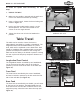
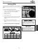
To rotate the spindle head horizontally, do these
steps:
1. UNPLUG THE MILL!
2. Make sure the spindle is stopped and the work area
is free from obstructions before proceeding.
3. Using a 17mm wrench, loosen the three locking nuts
shown in Figure 14.
4. Push or pull the spindle head to swivel it to the
desired position. Use the scale located on the
column to set the angle desired.
5. Tighten the three nuts to lock the headstock in
position.
Figure 14. Vertical and horizontal
headstock lock nuts.
Vertical Lock Nuts
Horizontal Lock Nuts
The table can be moved in 3 axes. Each axis is
independently controlled by a handle or handwheel. The
longitudinal travel has the added feature of a power
feed, which will be explained in more detail later. Each
handle or handwheel has a graduated dial to accurately
position the workpiece in relation to the cutting tool.
Each axis has the ability to be locked in position. Locking
the axis in place will help keep workpiece vibration to a
minimum.
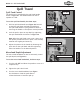
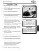
Longitudinal Feed Control
The longitudinal feed is controlled by two handwheels,
one at each end of the table, and can be locked in
position by the two locks at the front of the table (see
Figure 15).
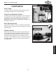
Cross Feed
The cross feed is controlled by the center handwheel,
and can be locked in position by the lock under the left
side of the mill table (see Figure 16).
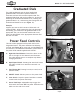
Knee Feed
The knee feed is controlled by one handle, just off center
at the front of the machine. The Model M1001 has one
knee feed lock on the left side of machine next to the
single shot pump, where the knee meets the ways (see
Figure 16).
Table Travel
Figure 15. Longitudinal locks.
Figure 16. Cross and knee locks.
Cross Lock
Knee Lock
Longitudinal Locks