
Specifications


-22-
Model W1811 (For Machines Mfd. Since 6/14)
SETUP
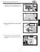
12. Slide the rip fence base on the rail, and check the
spacing between the rip fence base and scale bar
(see Figure 19). There should be a minimum of
1
⁄8"
of space between the scale bar and the fence base.
Adjust the mounting position of the rip fence rail
to create this space evenly along the length of the
scale bar, then tighten the rail mounting nuts.
Figure 19. Fence base installed; spacing
between fence base and scale bar.
Spacing
Note: The fence should slide smoothly on the rail;
if it doesn't, remove the fence base and adjust the
spring pressure plate mounting position on the fence
base (see Figure 20), by loosening the two screws
and repositioning the pressure plate slightly.
Figure 21. Rip fence installed on fence
base.
T-Bar
Rip Fence
Lock Levers
13. Thread the rip fence lever into the fence base
(Figure 20), tighten the hex nut against the rip
fence base to keep the lever in place.
14. Slide the rip fence on the fence base T-bar as
shown in Figure 21. Use the two lock levers on the
opposite side of the fence base to secure the fence
in position.
Figure 20. Location of spring pressure
plate for fence slide adjustments.
Rip Fence
Lever
Spring Pressure
Plate