MODEL M1109 COMBO LATHE/MILL OWNER'S MANUAL Phone: (360) 734-3482 • Online Technical Support: tech-support@shopfox.biz COPYRIGHT © JULY 2006 BY WOODSTOCK INTERNATIONAL, INC. #8232CR WARNING: NO PORTION OF THIS MANUAL MAY BE REPRODUCED IN ANY SHAPE OR FORM WITHOUT THE WRITTEN APPROVAL OF WOODSTOCK INTERNATIONAL, INC.
����������������������������������������������������������������������� �������������������������������������������������������������� ���������������������������������������������������������������������� �������������������������������������������������������������������� ������������������������ ����������������������������������������������������������������������� ������������������������������������������������������������������������ �������������������������������������������������������������������
ELECTRICAL ......................................................................................................9 220V Operation ............................................................................................. 9 Extension Cords ............................................................................................ 9 Grounding ................................................................................................... 9 ELECTRICAL SETUP ............................................
INTRODUCTION SAFETY ELECTRICAL SETUP OPERATIONS MAINTENANCE SERVICE PARTS MILLING OPERATIONS ........................................................................................ 30 Installing Tools ............................................................................................30 Removing Tools ............................................................................................30 Headstock Positioning ..................................................................................
INTRODUCTION Woodstock Technical Support Your new SHOP FOX® Model M1109 Combo Lathe/Mill has been specially designed to provide many years of trouble-free service. Close attention to detail, ruggedly built parts and a rigid quality control program assure safe and reliable operation. Woodstock International, Inc. is committed to customer satisfaction. Our intent with this manual is to include the basic information for safety, setup, operation, maintenance, and service of this product.
INTRODUCTION M1109 Combo Lathe/Mill Controls and Features I G D B A C K F L H E J M AA Z N Y O X P Q W V U T S R M1109 Combo Lathe/Mill. A. B. C. D. E. F. G. H. I. J. K. L. M. N. O. P. Q. R. S. T. U. V. W. X. Y. Z. AA.
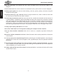
M1109 Combo Lathe/Mill SAFETY Indicates an imminently hazardous situation which, if not avoided, WILL result in death or serious injury. Indicates a potentially hazardous situation which, if not avoided, COULD result in death or serious injury. Indicates a potentially hazardous situation which, if not avoided, MAY result in minor or moderate injury.
M1109 Combo Lathe/Mill 12. Do not force tool. The machine will do a safer and better job at the rate for which it was designed. SAFETY 13. Use correct tool. Do not force machine or attachment to do a job for which it was not designed. 14. Wear proper apparel. Do not wear loose clothing, neck ties, gloves, jewelry, and secure long hair away from moving parts. 15. Remove chuck keys, rags, and tools. Before turning the machine on, make it a habit to check that all chuck keys and wrenches have been removed.
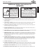
M1109 Combo Lathe/Mill Additional Safety Instructions for Lathe/Mills USE this and other machinery with caution and respect. Always consider safety first, as it applies to your individual working conditions. No list of safety guidelines can be complete—every shop environment is different. Failure to follow guidelines could result in serious personal injury, damage to equipment or poor work results. 1. UNDERSTANDING THE MACHINE: Read and understand this manual before operating machine. 2.
M1109 Combo Lathe/Mill SAFETY Avoiding Potential Injuries Figure 1. Always protect the bed ways, and unplug the lathe/mill when retooling. Figure 3. Always wear face and eye protection when using this lathe/mill. Figure 2. Never walk away from the lathe/mill leaving the chuck key inserted in the chuck. Figure 4. Never use hands to stop or slow the chuck when shutting down the lathe/mill. Figure 5. Never wear loose clothing or gloves when working with the lathe/mill.
M1109 Combo Lathe/Mill ELECTRICAL 220V Operation The SHOP FOX® MODEL M1109 Combo Lathe/Mill operates at 220 volt single-phase only. Only connect this machine to a dedicated circuit (wire, breaker, plug, receptacle) with a verified ground, using the recommended circuit size and NEMA 6-20 plug/receptacle (Figure 6) listed at the bottom of this page.
M1109 Combo Lathe/Mill Inventory SETUP The following is an inventory of the accessories shipped with your SHOP FOX® Model M1109 Lathe/Mill. A SETUP Qty. Installed Accessories (Figure 7) A. 6" Three-Jaw Chuck .......................................1 B. 4-Way Tool Post and Compound Rest ..................1 C. Follow Rest .................................................1 D. Compound Rest ............................................1 Packaged Accessories (Figure 8) E. 8" Four-Jaw Universal Chuck ........
M1109 Combo Lathe/Mill Cleaning Machine The ways and other unpainted parts of your lathe/mill are coated with a waxy grease that protects them from corrosion during shipment. Clean this grease off with a solvent cleaner or citrus-based degreaser. DO NOT use chlorine-based solvents such as brake parts cleaner, lacquer thinner, or acetone—if you happen to splash some onto a painted surface, you will ruin the finish. Machine Placement Floor Load: Your lathe/mill is a heavy load (1200 lbs.
M1109 Combo Lathe/Mill Uncrating and Lifting This lathe/mill has been carefully crated. If you notice it has been damaged, contact your authorized SHOP FOX® dealer immediately. To unpack and move the lathe/mill, do these steps: 1. Read Pages 9 & 11 to prepare the lathe/mill location, and install or prepare holes for any floor mounting fasteners (Figure 11). 2. Gather the following items: • Fork Lift or 2-ton hoist, and driver or operator. • 1 Ton lifting straps and hooks.
M1109 Combo Lathe/Mill Test Run and Break-In The purpose of the test run is to make sure the lathe/ mill and safety features operate correctly before proceeding with additional setup. To begin the test run procedure, do these steps: Make sure the lathe/mill is lubricated and headstock oil level is full. Refer to Page 34 if required. 2. Make sure the chuck is bolted to the spindle. 3.
M1109 Combo Lathe/Mill LATHE OPERATIONS General NOTICE Complete the Test Run and Break-In procedure on Page 13 before using this lathe/mill for any cutting or threading operations; otherwise, gear box damage will occur. The Model M1109 will perform many types of operations that are beyond the scope of this manual. Many of these operations can be dangerous or deadly if performed incorrectly. Always wear safety glasses when operating this lathe/mill.
M1109 Combo Lathe/Mill Chuck and Faceplate Mounting The three-jaw scroll chuck has hardened steel jaws that self-center the workpiece within 0.002"-0.003". An extra set of jaws is included for machining larger workpieces. The four-jaw chuck also has hardened steel jaws but are adjusted independently to hold an off-center workpiece. Each jaw can be removed from the chuck body and reversed for special clamping applications. The cast-iron faceplate has slots for T-bolts that hold clamping fixtures.
M1109 Combo Lathe/Mill Replacing Jaws The three-jaw scroll chuck has removable hardened steel jaws (Figure 17). The outside of the jaws are used to hold the workpiece from the outer diameter. Numbered from 1–3, the jaws must be used in the matching numbered jaw guides, see Figure 18. Note: The chuck need not be removed from the spindle to swap the jaws. OPERATIONS To remove a set of jaws, do these steps: 1. DISCONNECT POWER TO THE LATHE/MILL! 2.
M1109 Combo Lathe/Mill Using the Four-Jaw Chuck To install the four-jaw chuck, do these steps: Refer to the Three-Jaw Direct Mount Scroll Chuck procedures on Page 15 to mount the four-jaw chuck. To load a workpiece in the four-jaw chuck, do these steps: Using the chuck key, open each jaw so the workpiece will lay flat against the chuck face. 2. Support the workpiece. 3.
M1109 Combo Lathe/Mill Using the Faceplate The faceplate can be used to turn non-cylindrical parts or for off-center turning by clamping the workpiece to the faceplate. To install the faceplate, do these steps: Refer to the Three-Jaw Direct Mount Scroll Chuck procedures on Page 15 to mount the faceplate. To load a workpiece, do these steps: 1. Support the workpiece. 2. Slide the tailstock to the workpiece. 3.
M1109 Combo Lathe/Mill Using the Tailstock The tailstock (Figure 23) can be used to support workpieces with the use of a live or dead center. Using an MT#3 drill chuck and a drill bit, the lathe can drill or bore holes in the center of a part. The tailstock can also be offset for cutting shallow tapers. Quill Feed Quill Lock Lever Tailstock Lock Lever To use the tailstock, do these steps: 1. Slide the tailstock to the desired position. 2.
M1109 Combo Lathe/Mill Cutting Shallow Tapers with the Tailstock To setup the tailstock to cut tapers, do these steps: 1. Lock the tailstock in position. 2. Alternately loosen and tighten the left and right offset adjustment screws until the desired offset is indicated on the scale (see Figures 25 & 26). 3. Retighten the lock screw. Note: To return the tailstock back to the original position, repeat the process until the centered position is indicated on the scale.
M1109 Combo Lathe/Mill 5. Place the live center in the tailstock. 6. Attach a lathe/mill dog to the bar stock and mount it between centers. 7. Turn approximately 0.010" off the diameter. 8. Measure the stock with a micrometer. • If the stock diameter is thicker at the tailstock end, the tailstock needs to be moved toward you half the distance of the amount of the taper (see Figure 28).
M1109 Combo Lathe/Mill Using Centers The dead center is used in the tailstock and lathe spindle to support workpieces. When used in the tailstock, make sure to keep the MT#3 dead center tip and workpiece lubricated to prevent tip galling. This lathe/mill is also supplied with an MT#5 dead center that fits into the lathe spindle taper. To install a dead or live center, do these steps: 1. Feed the quill out about 1" and insert the MT#3 dead center (Figure 30). The mating tapers provide the locking action.
M1109 Combo Lathe/Mill Using the Steady Rest The steady rest serves as a support for long shafts. The steady rest can be placed anywhere along the length of the ways. Clamp Knob To use the steady rest, do these steps: 1. Carefully place the steady rest on the lathe bedways. 2. Loosen the lock knobs so the finger position can be adjusted (see Figure 32). 3. Loosen the clamp knob (see Figure 32) and open the steady rest so a workpiece can fit inside of the fingers.
M1109 Combo Lathe/Mill Setting Compound Slide The compound slide is used to cut tapers on parts or to set the proper infeed angle when threading. It may also be used to cut specific lengths longitudinally, when set parallel to the spindle axis. To set the angular position, do these steps: 1. Loosen the hex nuts, one on each side of the compound slide (see Figure 34). 2. Rotate the compound slide to the desired angular position using the scale. 3. Tighten the two hex nuts.
M1109 Combo Lathe/Mill Using Manual Feed You can manually move the cutting tool around the lathe/ mill with the three handwheels shown in Figure 36. Longitudinal Handwheel The longitudinal handwheel moves the carriage left or right along the bed. This control is helpful when setting up the machine for turning or when manual movement is desired during turning operations.
M1109 Combo Lathe/Mill Setting RPM To determine and set the needed cutting RPM, do these steps: 1. 2. Use the table in Figure 37 to determine the cutting speed required for the workpiece material. Determine the average final diameter of the workpiece in inches, for the cut to be made. Failure to follow RPM and feed rate guidelines may threaten operator safety from ejected parts or broken tools. 3.
M1109 Combo Lathe/Mill Setting Power Feed Rate The carriage has longitudinal and cross slide power feed capabilities. All directions reverse when spindle rotation is reversed. M N NOTICE Feed rate is based on spindle RPM. High feed rates combined with high spindle speeds result in a rapidly moving carriage or cross slide. Pay close attention to the feed rate you have chosen and be ready to disengage the apron. Failure to do this may cause the carriage to crash into the chuck.
M1109 Combo Lathe/Mill Threading Setup Your lathe is capable of cutting inch and metric threads. To setup for threading, do these steps: 1. DISCONNECT THE LATHE/MILL FROM POWER! 2. Refer to the Change Gear Chart on Page 29 or the chart on the inside of the change gear door to determine the needed combination of gears and which spindle location to install each gear on.
M1109 Combo Lathe/Mill Change Gear Chart OPERATIONS -29-
M1109 Combo Lathe/Mill MILLING OPERATIONS Installing Tools To install a tool in the spindle, do these steps: 1. DISCONNECT THE LATHE/MILL FROM POWER! 2. Carefully clean the surface of the arbor and spindle taper. Ensure that they are free of debris and burrs. 3. Insert the arbor into the spindle, and rotate the arbor so the slot in the arbor lines up with the pin inside of the spindle. 4. Press the arbor up firmly to seat it with the spindle. 5.
M1109 Combo Lathe/Mill Headstock Positioning The mill headstock head can be raised and lowered vertically, or rotated left or right up to 90º degrees to position the cutting tool next to the workpiece. To position the spindle head vertically, do these steps: 1. Make sure the spindle is stopped and the work area is free from obstructions before proceeding. 2. Loosen both column lock levers so that the headstock can freely slide on the column (Figure 47). 3.
M1109 Combo Lathe/Mill Table Travel The mill table of the Model M1109 can be moved in two axes—cross feed and longitudinal feed. Each of these axes are controlled by graduated handwheels to accurately position the workpiece in relation to the tool. To set the power feed for milling, refer to Setting Power Feed Rate on Page 27. Leadscrew Lever Cross Feed The cross feed is controlled by the cross feed handwheel of the lathe shown in Figure 50.
M1109 Combo Lathe/Mill Setting RPM When using the milling machine, determine the RPM needed to cut your workpiece, and adjust the gear change levers to achieve the closest RPM. NOTICE Never shift gears while lathe or mill is running; otherwise, the gear teeth will be chipped or broken. NOTICE Failure to follow RPM and Feed Rate Guidelines will put undue strain on moving parts, shorten tool life, poor workpiece results and may threaten operator safety from ejected parts or broken tools.
M1109 Combo Lathe/Mill MAINTENANCE General Maintenance Headstock Oil Fill Regular periodic maintenance of your lathe/mill will ensure optimum performance. Make a habit of inspecting your machine each time you use it. Check for the following conditions and repair or replace when necessary: • • • • Loose mounting bolts and chuck. Worn switch or safety features. Worn or damaged cords and plugs. Any other condition that could hamper the safe operation of this machine. Figure 53. Headstock fill plug.
M1109 Combo Lathe/Mill For daily lubrication, use a manual oil gun with a general 10W machine oil to lubricate the following 15 ball oiler fittings. See Figure 56 for some typical locations.
M1109 Combo Lathe/Mill SERVICE Cross Slide Backlash Backlash is the amount of play found in a lead screw. It can be found by turning the cross slide handwheel in one direction, and then turning the handwheel the other direction. When the cross slide begins to move, the backlash has been taken up. Cross Feed Backlash Adjustment Cap Screw Note: Avoid the temptation to overtighten the cross slide backlash screw. Overtightening will cause excessive wear to the sliding block and lead screw.
M1109 Combo Lathe/Mill Electrical Component and Connection Index (This page is available online in color at: www.shopfoxtools.com) (KM1) Main System Contactor See Figure 63 Figure 65 (KM2, KM3) Spindle Motor Direction Contactors Figure 68 Figure 73 (TC) Transformer Figure 72 Figure 64 Figure 66 Figure 67 SERVICE Figure 62. M1109 Electrical panel.
M1109 Combo Lathe/Mill Electrical Connections (This page is available online in color at: www.shopfoxtools.com) Figure 63. Contactor wiring (KM1). Figure 65. Contactor wiring (KM2 and KM3). Figure 64. Junction block wiring. SERVICE Figure 66. Junction block wiring. Figure 67. Junction block wiring. -38- Figure 68. Contactor wiring (KM2 and KM3).
M1109 Combo Lathe/Mill Electrical Connections (This page is available online in color at: www.shopfoxtools.com) Figure 72. Transformer connection. Figure 69. Motor connection. Figure 73. Transformer connection. Figure 70. Start capacitor. SERVICE Figure 71. Mill power switch. Figure 74. Lathe motor direction limit switches.
M1109 Combo Lathe/Mill Electrical Connections Emergency Stop Switch Power Lamp Jog Button Figure 75. Lathe controls. Figure 76. Lathe control panel wiring.
M1109 Combo Lathe/Mill Troubleshooting This section covers the most common lathe problems. DO NOT make any adjustments until the lathe is disconnected from power and all moving parts have come to a complete stop. Motor & Electrical SYMPTOM Motor will not start. POSSIBLE CAUSE CORRECTIVE ACTION 1. Use the spindle direction ON/OFF lever. 2. Turn the main power switch ON at the back of the lathe. 3. Rotate emergency switch so it pops out. 4.
M1109 Combo Lathe/Mill Operation and Work Results SYMPTOM POSSIBLE CAUSE CORRECTIVE ACTION 1. Workpiece is unbalanced. Entire machine vibrates exces2. Worn or broken gear present. sively upon startup and while 3. Chuck or faceplate has become unbalanced. running. 4. Spindle bearings badly worn. 1. Reinstall workpiece so it is as centered with the spindle bore as possible. 2. Inspect gears and replace if necessary. 3. Rebalance chuck or faceplate; contact a local machine shop for help. 4.
M1109 Combo Lathe/Mill SYMPTOM POSSIBLE CAUSE CORRECTIVE ACTION Loud, repetitious noise coming from machine at or near the motor. 1. Pulley setscrews or keys are missing or loose. 1. Inspect keys and setscrews. Replace or tighten if necessary. 2. Tighten fan or shim cover, or replace items. 2. Motor fan is hitting the cover. Carriage hard to move. 1. Carriage lock is tightened down. 2. Chips have loaded up on bedways. 5. Gibs are too tight. 1. Check to make sure table locks are fully released. 2.
PARTS -44- 53 54 1 2 3 4 5 6 52 7 51 8 50 49 9 1 0 11 1 2 41 46 40 39 5-1 47 48 38 45 33 37 31 21 20 26 27 22 28 23 29 34 24 30 35 42 32 36 44 43 13 19 18 25 1 4-2 17 1 4-1 16 15 1 4-3 1 4-4 Change Gears 55-1 to 55-17 58 57 56 14 M1109 Combo Lathe/Mill Lathe Change Gear Housing Diagram (0000 Series Parts)
M1109 Combo Lathe/Mill 0000 Series Parts List REF PART�# DESCRIPTION REF PART�# DESCRIPTION 1 2 3 4 5 5-1 6 7 8 9 10 11 12 13 14 14-1 14-2 14-3 14-4 15 16 17 18 19 20 21 XPS38M XPLW02M XPN04M XM11090004 XM11090005 XM11090005-1 XPVA71 XM11090007 XPSS03M XPB07M XPLW04M XPW01M XM11090012 XM11090013 XM11090014 XM11090014-1 XM11090014-2 XM11090014-3 XM11090014-4 XM11090015 XM11090016 XM11090017 XPW04M XPN02M XM11090020 XM11090021 22 23 24 25 26 27 28 29 30 XM11090022 XPW06M XPEC12M XM11090025 XM11090026
-46- 1007 1009 1010 1011 1008 1017 1100 1101 1032 1031 1019 1080 1081 1079 1075 1007 1077 1078 1045 1052 1044 1043 1042 1041 1040 1035 1036 1054 1053 1046 1047 1070 1064 1065 1066 1067 1068 1069 1007 1058 1057 1056 1055 1039 1051 1007 1038 1049 1037 1048 1022 1024 1026 7 1020 1028 100 1030 1021 1027 1023 1025 1034 1033 1072 1073 1074 1018 1071 1013 1014 1015 1016 1102 101 2 1090 1091 1092 1093 1094 1007 1105 1007 1098 1096 1096-1 1088 1007 1084 1082 1110 110 8 1107 11 0 9 109
M1109 Combo Lathe/Mill 1000 Series Parts List PART�# DESCRIPTION REF PART�# XM11091001 XM11091002 XPW08M XPK08M XM11091005 XM11091006 XPSB33M XM11091008 XM11091009 XPR06M XM11091011 XM11091012 XM11091013 XM11091014 XPSB13M XM11091016 XM11091017 XM11091018 XM11091019 XM11091020 XM11091021 XM11091022 XM11091023 XPK13M XPR07M XM11091011 XM11091027 XM11091028 XPSS03M XPR78M XM11091032 XM11091033 XM11091034 XM11091035 XM11091036 XM11091037 XPB42M XM11091039 XPR09M XM11091041 XM11091042 XPR09M XM11091044 XPK
PARTS -48- 2003 2048 2047 2046 2045 2044 2049 2050 2051 2001 2002 2004 2043 2005 2014 2042 2039 2040 2024 2018 2025 2026 2027 2017 2016 2015 2038 2041 2037 2021 2022 2023 2013 2036 2012 2035 2007 2011 2006 2010 2008 2009 2020 2034 2033 2032 2031 2030 2029 2028 2019 M1109 Combo Lathe/Mill Leadscrew Gearbox Diagram (2000 Series Parts)
M1109 Combo Lathe/Mill 2000 Series Parts List REF PART�# DESCRIPTION REF PART�# DESCRIPTION 2001 2002 2003 2004 2005 2006 2007 2008 2009 2010 2011 2012 2013 2014 2015 2016 2017 2018 2019 2020 2021 2022 2023 2024 2025 2026 XM11092001 XPS05M XM11092003 XM11092004 XM11092005 XPK08M XM11092007 XM11092008 XM11092009 XM11092010 XM11092011 XPK127M XM11092013 XM11092014 XM11092015 XM11092016 XM11092017 XM11092018 XM11092019 XPS07M XPR06M XM11092022 XPK126M XM11092024 XP51102 XM11092026 COVER�PLATE PHLP�HD�
M1109 Combo Lathe/Mill Compound Rest and Tool Post Diagram (2500 Series Parts) ���� ���� ���� ���� ���� ���� ���� ���� ���� ���� ���� ���� ���� ���� ���� ���� ���� ���� ���� ���� ���� ���� ���� ���� ���� ���� ���� ���� ���� ���� ���� ���� ���� ���� ���� ���� PARTS ���� ���� ���� -50-
M1109 Combo Lathe/Mill 2500 Series Parts List REF PART�# DESCRIPTION REF PART�# DESCRIPTION 2501 2502 2503 2504 2505 2506 2507 2508 2509 2510 2511 2512 2513 2514 2515 2516 2517 2518 2519 2520 XM11092501 XM11092502 XM11092503 XM11092504 XM11092505 XM11092506 XM11092507 XM11092508 XM11092509 XPSS64M XPN01M XPSS01M XM11092513 XM11092514 XM11092515 XPSB01M XM11092517 XM11092518 XM11092519 XM11092520 FEMALE�KNOB�5/16-18 LEVER�5/16-20 TOOL�POST�BOLT�M10-1.
PARTS 3073 3072 3079 3078 -52- 3074 3070 3071 3072-1 3076 3077 3075 3064 3001 3062 3085 3084 3063 3069 3065 3066 3067 3068 3061 3083 3081 3080 3082 3059 3060 3058 3054 3055 3056 3057 3052 3053 3018 3020 3019 30273028 3030 3029 3031 3032 3033 3034 3036 3035 3037 3038 3021 3022 3023 3024 3025 3 304 039 3026 0 3041 3017 3011 3012 3013 3010 3014 3008 3015 3009 3016 3006 3007 3043 3042 3051 3045 3044 3046 3047 3049 3048 3050 3004 3002 3003 3005 M1109 Combo Lathe/Mill Bed D
M1109 Combo Lathe/Mill 3000 Series Parts List REF PART�# DESCRIPTION REF PART�# DESCRIPTION 3001 3002 3003 3004 3005 3006 3007 3008 3009 3010 3011 3012 3013 3014 3015 3016 3017 3018 3019 3020 3021 3022 3023 3024 3025 3026 3027 3028 3029 3030 3031 3032 3033 3034 3035 3036 3037 3038 3039 3040 3041 3042 3043 XM11093001 XM11093002 XM11093003 XPSB11M XM11093005 XM11093006 XPS08M XPSS12M XPN01M XPSB48M XM11093011 XM11093012 XPSB07M XPSB30M XPB47M XM11093016 XPFH07M XM11093018 XPSS09M XPN03M XM11093021 XM1
M1109 Combo Lathe/Mill Steady Rest and Follow Rest Diagram (3500 Series Parts) ���� ���� ���� ���� ���� ���� ���� ���� ���� ���� ���� ���� ���� ���� ���� ���� ���� ���� ���� ���� ���� ���� ���� ���� ���� ���� ���� ���� ���� ���� ���� ���� PARTS ���� -54-
M1109 Combo Lathe/Mill 3500 Series Parts List REF PART�# DESCRIPTION REF PART�# DESCRIPTION 3501 3502 3503 3504 3505 3506 3507 3508 3509 3510 3511 3512 3513 XM11093501 XM11093502 XM11093503 XM11093504 XM11093505 XPN01M XM11093507 XM11093508 XM11093509 XM11093510 XPW01M XM11093512 XM11093513 PINNED�KNOB ADJUSTMENT�STUD TAPERED�PIN BRASS-TIPPED�FINGER SPECIAL�SET�SCREW�M6-1 HEX�NUT�M6-1 THUMB�KNOB�M6-1.
4078 4001 4002 PARTS 4075 4006 4076 4077 4005 4004 4003 -564073 4072 4071 4068 4059 4060 4069 4064 4079 4056 4054 4055 4053 4063 4058 4052 4051 4050 4033 4032 4061 4062 4022 4021 4020 4019 4023 4057 4017 4018 4016 4015 4014 4067 4066 4065 4013 4070 4012 4011 4010 4008 4009 4074 4007 4024 4036 4037 4043 4044 4045 4042 4046 4041 4047 4048 4049 4035 4034 4030 4031 4028 4029 4027 4026 4025 4040 4039 4038 M1109 Combo Lathe/Mill Apron Diagram (4000 Series P
M1109 Combo Lathe/Mill 4000 Series Parts List REF PART�# DESCRIPTION REF PART�# DESCRIPTION 4001 4002 4003 4004 4005 4006 4007 4008 4009 4010 4011 4012 4013 4014 4015 4016 4017 4018 4019 4020 4021 4022 4023 4024 4025 4026 4027 4028 4029 4030 4031 4032 4033 4034 4035 4036 4037 4038 4039 4040 XPK81M XM11094002 XM11094003 XM11094004 XM11094005 XM11094006 XM11094007 XM11094008 XM11094009 XM11094010 XPR09M XM11094012 XM11094013 XM11094014 XM11094015 XM11094016 XPSB79M XM11094018 XPR03M XPK29M XM11094021
M1109 Combo Lathe/Mill Tailstock Diagram (5000 Series Parts) 5015 5016 5023 5017 5020 5018 5026 5025 5024 5027 5028 5029 5022 5021 5019 5014 5030 5013 5012 5039 5031 5011 5010 5032 5040 5033 5041 5009 5034 5008 5007 5006 5035 5005 5004 5003 5036 5002 5001 5037 PARTS 5038 -58-
M1109 Combo Lathe/Mill 5000 Series Parts List REF PART�# DESCRIPTION REF PART�# DESCRIPTION 5001 5002 5003 5004 5005 5006 5007 5008 5009 5010 5011 5012 5013 5014 5015 5016 5017 5018 5019 5020 5021 XM11095001 XM11095002 XM11095003 XM11095004 XPR03M XM11095006 XPSB12M XM11095008 XM11095009 XM11095010 XM11095011 XM11095012 XM11095013 XM11095014 XM11095015 XM11095016 XM11095017 XM11095018 XM11095019 XPK125M XM11095021 SPECIAL�SET�SCREW�M5-.
M1109 Combo Lathe/Mill Mill Column Diagram (6000 Series Parts) 6014 6013 6017 6012 6015 6018 6016 6011 6010 6009 6008 6030 6019 6029 6028 6027 6026 6020 6021 6025 6007 6022 6006 6005 6023 6024 6004 6003 6002 PARTS 6001 -60-
M1109 Combo Lathe/Mill 6000 Series Parts List REF PART�# DESCRIPTION REF PART�# DESCRIPTION 6001 6002 6003 6004 6005 6006 6007 6008 6009 6010 6011 6012 6013 6014 6015 XM11096001 XM11096002 XPLW05M XPSB92M XPLW05M XPSB119M XM11096007 XM11096008 XPSB02M XP8106 XM11096011 XM11096012 XM11096013 XPN41M XM11096015 PEDESTAL TAPER�PIN LOCK�WASHER�12MM CAP�SCREW�M12-1.75�X�40 LOCK�WASHER�12MM CAP�SCREW�M12-1.
-62- 7027 7020 7019 7001 7017 7088 7016 7015 7014 7026 7025 7013 7018 7009 7010 7021 7011 7022 7023 7012 7024 7002 7003 7004 7005 7006 7007 7008 PARTS 7042 7041 7040 7039 7038 7034 7035 7033 7032 7089 7031 7030 7029 7028 7037 7036 7043-4 7043-5 7043 7043-1 7046 7084 7083 7082 7081 7085 7047 7044 7045 7043-2 7043-3 7080 7086 7079 7050 7049 7048 7087 7078 7059 7058 7057 7056 7055 7054 7052 7053 7051 7077 7076 7075 7074 7073 7071 7072 7070 706
M1109 Combo Lathe/Mill 7000 Series Parts List REF PART�# DESCRIPTION REF PART�# DESCRIPTION 7001 7002 7003 7004 7005 7006 7007 7008 7009 7010 7011 7012 7013 7014 7015 7016 7017 7018 7019 7020 7021 7022 7023 7024 7025 7026 7027 7028 7029 7030 7031 7032 7033 7034 7035 7036 7037 7038 7039 7040 7041 7042 7043 7043-1 7043-2 7043-3 7043-4 XPR12M XM11097002 XM11097003 XM11097004 XM11097005 XM11097006 XPR12M XM11097008 XM11097009 XM11097010 XPFH31M XM11097012 XM11097013 XM11097014 XM11097015 XM11097016 XM11
M1109 Combo Lathe/Mill Accessories and Labels Diagram (8000 Series Parts) 8004 8016 8013 8020 8009 8014 8017 8018 8005 8048 8006 8015 8008 8010 8033 8022 8001 8012 8007 8047 8046 8045 8042 8023 8044 8021 8011 8039 8040 8041 8038 8024 8037 8034 8032 8025 8026 8030 8043 PARTS 8028 8035 8036 -64- 8027 8031 8029
M1109 Combo Lathe/Mill 8000 Series Parts List REF PART�# DESCRIPTION REF PART�# DESCRIPTION 8001 8004 8005 8006 8007 8008 XM11098001 XM11098004 XM11098005 XM11098006 XM11098007 XM11098008 8008-1 8008-2 8008-3 8008-4 8009 8009-1 8009-2 8009-3 8009-4 8010 8011 8012 8013 8014 8015 8016 8017 8018 8020 8021 XM11098008-1 XM11098008-2 XM11098008-3 XM11098008-4 XM11098009 XPAW02M XPAW04M XPAW06M XPAW08M XM11098010 XM11098011 XM11098012 XM11098013 XM11098014 XM11098015 XM11098016 XM11098017 XM11098018 XM11
M1109 Combo Lathe/Mill Main Wiring Box Diagram (9000 Series Parts) 9006 9007 9001 9002 9004 9003 9008 9011 9009 9010 9000 Series Parts List REF PART�# 9001 XM11099001 CONTACTOR� (LC1-D0910,�B5,�24V,�50HZ)� XM11099002 CONTACTOR� (LC1-D1201,�B5,�24V,�50HZ)� XM11099003 CONTACTOR� (LC1-D1201,�B5,�24V,�50HZ)� XM11099004 TRANSFORMER��(JBK5-63),� (INPUT�220V�+/-�5%,�OUTPUT�24V) 9002 9003 PARTS 9004 DESCRIPTION -66- REF PART�# DESCRIPTION 9006 9007 9008 9009 9010 9010-1 9011 XM11099006 XM11099
M1109 Combo Lathe/Mill Notes PARTS -67-
M1109 Combo Lathe/Mill Warranty Woodstock International, Inc. warrants all SHOP FOX® machinery to be free of defects from workmanship and materials for a period of two years from the date of original purchase by the original owner. This warranty does not apply to defects due directly or indirectly to misuse, abuse, negligence or accidents, lack of maintenance, or reimbursement of third party expenses incurred. Woodstock International, Inc.
Warranty Registration Name ___________________________________________________________________________________ Street __________________________________________________________________________________ City _________________________ State ___________________________Zip ________________________ Phone # ______________________ Email __________________________Invoice # ___________________ Model #_________Serial #______________Dealer Name__________________Purchase Date___________ CUT ALONG DOTTED LINE The follo
FOLD ALONG DOTTED LINE Place Stamp Here WOODSTOCK INTERNATIONAL INC. P.O.