MODEL W1706 14" BANDSAW OWNER'S MANUAL (FOR MODELS MANUFACTURED SINCE 8/10) Phone: (360) 734-3482 • Online Technical Support: tech-support@shopfox.biz COPYRIGHT © JUNE, 2004 BY WOODSTOCK INTERNATIONAL, INC., REVISED NOVEMBER, 2010 (TS) 177335 WARNING: NO PORTION OF THIS MANUAL MAY BE REPRODUCED IN ANY SHAPE OR FORM WITHOUT THE WRITTEN APPROVAL OF WOODSTOCK INTERNATIONAL, INC.
This manual provides critical safety instructions on the proper setup, operation, maintenance, and service of this machine/tool. Save this document, refer to it often, and use it to instruct other operators. Failure to read, understand and follow the instructions in this manual may result in fire or serious personal injury—including amputation, electrocution, or death. The owner of this machine/tool is solely responsible for its safe use.
SAFETY................................................4 Standard Machinery Safety Instructions....... 4 Additional Safety for Bandsaws................. 6 MAINTENANCE..................................... 41 General........................................... 41 Cleaning.......................................... 41 Protecting Table................................. 41 Lubrication....................................... 41 SERVICE............................................. 42 General...........................
INTRODUCTION Model W1706 (Mfg. Since 8/10) INTRODUCTION Woodstock Technical Support This machine has been specially designed to provide many years of trouble-free service. Close attention to detail, ruggedly built parts and a rigid quality control program assure safe and reliable operation. Woodstock International, Inc. is committed to customer satisfaction. Our intent with this manual is to include the basic information for safety, setup, operation, maintenance, and service of this product.
INTRODUCTION Model W1706 (Mfg. Since 8/10) Controls and Features Refer to Figures 1–2 and the descriptions below to better understand the controls and features of the Model W1706. A G A. Blade Quick-Release Lever: Quickly releases or engages blade tension for blade changes. B. B F Blade Tracking Knob: Adjusts and locks the blade tracking. E C. Table Stop: Allows for returning the table to 0° quickly and accurately. C D.
Model W1706 (Mfg. Since 8/10) SAFETY SAFETY For Your Own Safety, Read Manual Before Operating Machine The purpose of safety symbols is to attract your attention to possible hazardous conditions. This manual uses a series of symbols and signal words intended to convey the level of importance of the safety messages. The progression of symbols is described below.
Model W1706 (Mfg. Since 8/10) NEVER STAND ON MACHINE. Serious injury or accidental contact with cutting tool may occur if machine is tipped. Machine may be damaged. STABLE MACHINE. Unexpected movement during operations greatly increases the risk of injury and loss of control. Verify machines are stable/secure and mobile bases (if used) are locked before starting. ONLY USE AS INTENDED. Only use machine for its intended purpose.
Model W1706 (Mfg. Since 8/10) SAFETY Additional Safety for Bandsaws READ and understand this entire manual before using this machine. Serious personal injury may occur if safety and operational information is not understood and followed. DO NOT risk your safety by not reading! Use this and other machinery with caution and respect. Always consider safety first, as it applies to your individual working conditions. No list of safety guidelines can be complete—every shop environment is different.
Model W1706 (Mfg. Since 8/10) POWER SUPPLY Circuit Requirements The machine must be properly set up before it is safe to operate. DO NOT connect this machine to the power source until instructed to do so in the "Test Run" portion of this manual. ELECTRICAL This machine must be connected to the correct size and type of power supply circuit, or fire or electrical damage may occur. Read through this section to determine if an adequate power supply circuit is available for this machine.
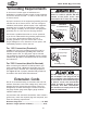
Model W1706 (Mfg. Since 8/10) Grounding Requirements ELECTRICAL In the event of certain types of malfunctions or breakdowns, grounding provides a path of least resistance for electric current to travel— in order to reduce the risk of electric shock. Improper connection of the equipment-grounding wire will increase the risk of electric shock. The wire with green insulation (with/without yellow stripes) is the equipmentgrounding wire.
Model W1706 (Mfg. Since 8/10) SETUP Unpacking This machine has been carefully packaged for safe transportation. If you notice the machine has been damaged during shipping, please contact your authorized Shop Fox dealer immediately. Inventory A The following is a description of the main components shipped with the Model W1706. Lay the components out to inventory them. B Note: If you can't find an item on this list, check the mounting location on the machine or examine the packaging materials carefully.
Model W1706 (Mfg. Since 8/10) SETUP Machine Placement • Floor Load: This machine distributes a heavy load in a small footprint. Some residential floors may require additional bracing to support both machine and operator. • Working Clearances: Consider existing and anticipated needs, size of material to be processed through the machine, and space for auxiliary stands, work tables or other machinery when establishing a location for your bandsaw.
Model W1706 (Mfg. Since 8/10) Setup Procedures Before connecting your bandsaw to power for the first time and performing the Test Run on Page 16, you MUST successfully complete the following tasks in the given order per the instructions on the referenced pages: 1. Assemble the bandsaw, as instructed on this page. 2. Connect the bandsaw to an adequate dust collection system (see Page 13). 3. Adjust the blade tracking, as instructed on Page 14.
Model W1706 (Mfg. Since 8/10) 5. Remove the insert and the table slot locking pin from the table. 6. Line up the table slot with the blade, position the table so that the blade is in the center cut-out. 7. Rotate the table so that the table slot faces to the right, then insert the table bolts through the mounting holes in the trunnion base, as shown in Figure 9. 8. 9. Secure the table by fully threading the two trunnion lock knobs onto the table bolts. Replace the table insert and locking pin.
Model W1706 (Mfg. Since 8/10) 12. Place the fence assembly onto the front rail and position it to the left of the table insert, then secure it in place by pressing down on the lock lever (see Figure 12). Lock Lever Figure 12. Fence secured in place. Dust Collection Recommended CFM at Dust Port:................. 400 CFM SETUP Do not confuse this CFM recommendation with the rating of the dust collector.
Model W1706 (Mfg. Since 8/10) Blade Tracking Blade tracking is affected by the tilt of the upper wheel (known as center tracking) and the alignment of both wheels (known as coplanar tracking). The wheels on this bandsaw were aligned at the factory, so center tracking is the only adjustment that needs to be performed when the saw is new (refer to Aligning Wheels on Page 47 for detailed instructions on coplanar tracking).
Model W1706 (Mfg. Since 8/10) 6. Rotate the upper wheel by hand several times (at least three) and watch how the blade rides on the wheel crown. See Figure 15 for an illustration of this concept. — If the blade rides in the center of the upper wheel and is centered on the peak of the wheel crown, then the bandsaw is already properly centertracked and no further tracking adjustments are needed at this time.
Model W1706 (Mfg. Since 8/10) Test Run Once the assembly is complete, test run your machine to make sure it runs properly. If, during the test run, you cannot easily locate the source of an unusual noise or vibration, stop using the machine immediately, then review the Troubleshooting on Page 52. If you still cannot remedy a problem, contact our Tech Support at (360) 734-3482 for assistance. SETUP To test run the machine, do these steps: 1.
Model W1706 (Mfg. Since 8/10) Tensioning Blade A properly tensioned blade is essential for making accurate cuts, extending the life of the blade, and making many other bandsaw adjustments. For instance, every time you replace the blade, you must perform this procedure because all blades tension differently. Note: Before you performed the Test Run, you set the blade to its approximate tension. The following procedure fine-tunes the blade tension to ensure accurate cutting results.
Model W1706 (Mfg. Since 8/10) Adjusting Positive Stop After using the table at a tilt of other than 0°, the positive stop allows the table to be quickly and accurately returned to the horizontal position in relation to the blade. This is important for accurate cutting results. Note: The height of the positive stop is lowered when the table is tilted to the left. Properly re-adjust the positive stop after returning the table to 0° or greater.
Model W1706 (Mfg. Since 8/10) Aligning Table To ensure cutting accuracy when the table is first installed, the table should be aligned so the miter slot is parallel to the bandsaw blade. This procedure works best with a 3⁄4" blade. Tools Needed Qty Wrench or Socket 10mm........................................1 Straightedge 24".................................................1 Fine Ruler 12"....................................................
Model W1706 (Mfg. Since 8/10) Aligning Miter Gauge Body To ensure accurate cutting results when using the miter gauge, the miter gauge body must be aligned with the blade. Tools Needed Qty Machinist's Square...............................................1 Phillips Screwdriver.............................................1 SETUP To align the miter gauge body, do these steps: 1.
Model W1706 (Mfg. Since 8/10) Adjusting Fence The fence must be aligned with the blade to ensure accurate cutting results. This is best done by aligning the fence with the miter slot after the table is properly aligned. Tools Needed Qty Hex Wrench 5mm................................................1 Wrench 10mm....................................................1 To align the fence with the miter slot, do these steps: DISCONNECT BANDSAW FROM POWER! 2.
Model W1706 (Mfg. Since 8/10) Adjusting Blade Support Bearings The support bearings are positioned behind the blade and support the back of the blade during cutting operations. Proper adjustment of the support bearings is an important part of making accurate cuts and also keeps the blade teeth from coming in contact with the guide bearings while cutting. There are support bearings on the upper lower blade guide assemblies—both sets adjust in the same manner.
Model W1706 (Mfg. Since 8/10) 7. 8. Loosen the thumbscrew on the support bearing adjustment shaft (see Figure 27). 0.016" Use the knurled knob to position the support bearing approximately 0.016" away from the back of the blade, as illustrated in Figure 29. Tip: For a quick gauge, fold a crisp dollar bill in half twice (four thicknesses of a dollar bill is approximately 0.016") and place it between the support bearing and the blade, as shown in Figure 30. 9.
Model W1706 (Mfg. Since 8/10) Adjusting Blade Guide Bearings The blade guides provide side-to-side support to keep the blade straight while cutting. The blade guides are designed to be adjusted in two ways—forward/backward and side-to-side. Properly adjusted blade guides are essential to making accurate cuts. Tools Needed Qty Hex Wrench 4mm................................................
Model W1706 (Mfg. Since 8/10) 7. Loosen the cap screws behind the guide bearings (see Figure 31), then open the upper wheel cover. 8. Rotate the upper wheel with one hand, and use the hex wrench to rotate the eccentric guide bearings until they just begin to rotate with the blade (see Figure 33). The guides should just lightly touch the blade. 9. When you are satisfied with blade guide bearing positions, re-tighten the cap screws behind them to secure the settings. Figure 33.
Model W1706 (Mfg. Since 8/10) OPERATIONS General This machine will perform many types of operations that are beyond the scope of this manual. Many of these operations can be dangerous or deadly if performed incorrectly. The instructions in this section are written with the understanding that the operator has the necessary knowledge and skills to operate this machine.
Model W1706 (Mfg. Since 8/10) Operation Overview The purpose of this overview is to provide the novice machine operator with a basic understanding of how the machine is used during operation, so the machine controls/components discussed later in this manual are easier to understand. Due to the generic nature of this overview, it is not intended to be an instructional guide.
Model W1706 (Mfg. Since 8/10) Basic Controls Refer to Figures 35–37 and the descriptions below to better understand the basic controls and components of this bandsaw. A. ON/OFF Buttons: Turns the motor ON and OFF. B. Upper Wheel Cover Knob: Enables access to the upper wheel compartment. A B C C. Fence and Miter Gauge: Allows for controlled cutting at various angles. OPERATIONS D. Upper Blade Guide Assembly: Supports the sides and back of the blade when cutting.
Model W1706 (Mfg. Since 8/10) Cutting Overview The Model W1706 is capable of performing the following cuts: • Miters • Angles • Resawing • Ripping • Crosscutting • • • • • Compound Angles Simple/Complex Curves Duplicate Parts Circles Beveled Curves Workpiece Inspection Some wood workpieces are not safe to cut or may require modification before they are safe to cut.
Model W1706 (Mfg. Since 8/10) • Wet or "Green" Stock: Cutting wood with a moisture content over 20% causes unnecessary wear on the blade and yields poor results. • Excessive Warping: Workpieces with excessive cupping, bowing, or twisting are dangerous to cut because they are unstable and can move unpredictably when being cut. DO NOT cut excessively warped wood. • Minor Warping: Workpieces with slight cupping can be safely supported if the cupped side faces the table or fence, as shown in Figure 39.
Model W1706 (Mfg. Since 8/10) Table Tilt The table tilts 45° to the right and 10° to the left for a wide range of cutting options. To tilt the table, do these steps: 1. DISCONNECT BANDSAW FROM POWER! 2. Loosen the two trunnion lock knobs underneath the table (see Figure 40), then use the tilt scale on the front of the trunnion to bring the table to the desired angle. Note: When tilting the table to the left, the positive stop must be lowered or removed.
Model W1706 (Mfg. Since 8/10) Ripping Ripping is the process of cutting with the grain of the wood stock. For plywood and other processed wood, ripping simply means cutting down the length of the workpiece. For ripping, a wider blade is better. In most ripping applications, a standard raker tooth style will be sufficient (refer to Blade Information on Page 37). To make a rip cut, do these steps: 1. Adjust the fence to match the width of the cut on your workpiece and lock the fence in place. 2.
Model W1706 (Mfg. Since 8/10) Crosscutting Crosscutting is the process of cutting across the grain of wood. For plywood and other processed wood, crosscutting simply means cutting across the width of the material. To make a 90˚ crosscut, do these steps: Mark the workpiece on the edge where you want to begin the cut. 2. Adjust the blade guide assembly to the correct height and make sure the miter gauge is set to 0° (or other angle for angled cuts). 3. Move the fence out of the way.
Model W1706 (Mfg. Since 8/10) Resawing Resawing (see Figure 44 for an example) is the process of cutting a board into two or more thinner boards. The maximum board width that can be resawn is limited by the maximum cutting height of the bandsaw. Maximum cutting height for this bandsaw is 6". The Model W1706 is capable of resawing, provided the saw is set up properly. Use common sense when resawing.
Model W1706 (Mfg. Since 8/10) Cutting Curves When cutting curves, simultaneously feed and turn the stock carefully so that the blade follows the layout line without twisting. Use either a narrower blade or a blade with more TPI (teeth per inch), or make more relief cuts, to avoid having to back the workpiece away from the blade, especially if the curve is sharp. Always make short cuts first, then proceed to the longer cuts. Relief cuts will also reduce the chance that the blade will be pinched or twisted.
Model W1706 (Mfg. Since 8/10) Blade Speed The Model W1706 offers blade speeds of 1500 & 3200 FPM (Feet Per Minute). For general woodworking and most cutting operations, we recommend using the 3200 FPM speed. Keep in mind, the results from different speeds are related to the type of blade being used. Whenever determining blade speed, also choose a type of blade that is related to your operation.
Model W1706 (Mfg. Since 8/10) Blade Information Selecting the right blade requires a knowledge of the various blade characteristics to match the blade with the particular cutting operation. Blade Length Measured by the circumference, blade lengths are usually unique to the brand of your bandsaw and the distance between wheels. This saw uses 92 1⁄2" to 93 1⁄2" long blades. Refer to Page 40 for blade replacements.
Model W1706 (Mfg. Since 8/10) Tooth Style Figure 49 illustrates the three main tooth styles: • • • Raker: Considered to be the standard because the tooth size and shape are the same as the tooth gullet. The teeth on raker blades usually are very numerous, have no angle, and produce cuts by scraping the material. As a result, smooth cuts can be achieved without cutting fast or generating more heat than other types. Skip: Similar to a raker blade that is missing every other tooth.
Model W1706 (Mfg. Since 8/10) Blade Changes To change the blade, do these steps: 1. DISCONNECT BANDSAW FROM POWER! 2. Put on heavy leather gloves and safety glasses. 3. Release the blade tension by moving the tension quick release lever all the way left. 4. Remove the table insert and the table locking pin (see Figure 50). 5. Adjust the upper and lower guide bearings as far away as possible from the blade. 6. Open the both wheel covers and slide the blade off of both wheels. 7.
Model W1706 (Mfg. Since 8/10) ACCESSORIES Bandsaw Accessories The following Bandsaw accessories may be available through your local Woodstock International Inc. Dealer. If you do not have a dealer in your area, these products are also available through online dealers. Please call or e-mail Woodstock International Inc. Customer Service to get a current listing of dealers at: 1-800-840-8420 or at sales@woodstockint.com.
Model W1706 (Mfg. Since 8/10) MAINTENANCE General Regular periodic maintenance on your machine will ensure its optimum performance. Make a habit of inspecting your machine each time you use it. On a daily basis, check for the following conditions and repair or replace when necessary: • • • • • • • Loose mounting bolts. Worn switch. Worn or damaged cords and plugs. Damaged or worn V-belt. Damaged or worn blade support and guide bearings. Damaged or glazed wheel rubber tires.
Model W1706 (Mfg. Since 8/10) SERVICE General This section covers the most common service adjustments or procedures that may need to be made during the life of your machine. If you require additional machine service not included in this section, please contact Woodstock International Technical Support at (360) 734-3482 or send e-mail to: tech-support@shopfox.biz. Redressing Rubber Tires As the bandsaw ages, the rubber tires may need to be redressed if they become hardened or glazed over.
Model W1706 (Mfg. Since 8/10) Belt Service To ensure optimum power transmission from the motor to the blade, the belt must be in good condition and operate under proper tension. The belt should be checked for cracks, fraying, and wear. Belt tension should be checked at least every 3 months—more often if the bandsaw is used daily. Pulley Checking Belt 1. DISCONNECT BANDSAW FROM POWER! 2. Open the lower wheel cover. 3. Note the condition of the belt.
Model W1706 (Mfg. Since 8/10) Replacing Belt Tools Needed Qty Socket 12mm w/Extension.....................................1 Wrench or Socket 13mm........................................1 To replace the belt, do these steps: 1. DISCONNECT BANDSAW FROM POWER! 2. Open both wheel covers, remove the bandsaw blade, and loosen the motor mount bolts shown in Figure 54 on the previous page. 3.
Model W1706 (Mfg. Since 8/10) Shimming Table To ensure accuracy when cutting stacked workpieces or circles, the table should be 90° to the back of the blade, as illustrated in Figure 56. If the table is not perpendicular to the back of the blade, the table will need to be shimmed. Items Needed Qty Wrench or Socket 10mm........................................1 Machinist's Square...............................................1 Metal Shims...........................................
Model W1706 (Mfg. Since 8/10) Blade Lead Bandsaw blades may wander off the cut line when sawing, as shown in Figure 58—this is called blade lead. Blade lead is usually caused by too fast of a feed rate, a dull or damaged blade, or improper blade tension. If your blade is sharp/undamaged, properly tensioned and you still have blade lead, perform the following procedures. Correcting Blade Lead 1. Use less pressure when feeding the workpiece through the cut. 2.
Model W1706 (Mfg. Since 8/10) Tool Needed Qty Wrench or Socket 10mm........................................1 The skew the table, do these steps: 1. On a scrap piece of wood, mark a line that is perpendicular to the front edge. Starting where the line begins, cut the board by pushing it through the blade with the miter gauge. 2. Loosen the six trunnion bolts that secure the table (see Figure 60).
Model W1706 (Mfg. Since 8/10) 3. With the blade installed and properly tensioned, hold a straightedge close to the center of both wheels. Make sure the straightedge fully extends across the wheels, as shown in Figure 61 on the previous page. — If the wheels are coplanar (see Figure 62, "A"), the straightedge will evenly touch the top and bottom of both wheels.
Model W1706 (Mfg. Since 8/10) Shimming a Wheel 1. DISCONNECT BANDSAW FROM POWER! 2. With a straightedge touching both points of whichever wheel is forward most, measure the distance the straightedge is away from the outof-adjustment upper wheel (see Figure 63 for an example). 3. Remove the blade from the saw, then remove the wheel that needs to be shimmed. 4. Determine the amount of shim washers necessary to compensate for the distance measured in Step 3, then place them on the wheel shaft. 5.
Model W1706 (Mfg. Since 8/10) Electrical Safety Instructions These pages are current at the time of printing. However, in the spirit of improvement, we may make changes to the electrical systems of future machines. Study this diagram carefully. If you notice differences between your machine and these wiring diagrams, call Woodstock International Technical Support at (360) 734-3482. 1. 2. 3. 4. SHOCK HAZARD. Working on wiring that is connected to a power source is extremely dangerous.
Model W1706 (Mfg.
Model W1706 (Mfg. Since 8/10) Troubleshooting This section covers the most common problems and corrections with this type of machine. WARNING! DO NOT make any adjustments until power is disconnected and moving parts have come to a complete stop! PROBLEM POSSIBLE CAUSE corrective action Motor will not start. 1. Low voltage. 2. Open circuit in motor or loose connections. 3. Faulty start capacitor. 1. Check power supply for proper voltage. 2.
Model W1706 (Mfg.
Model W1706 (Mfg.
Model W1706 (Mfg.
Model W1706 (Mfg.
Model W1706 (Mfg.
Model W1706 (Mfg.
Model W1706 (Mfg.
Fold along dotted lIne place stamp Here Woodstock international inc. p.o.
WARRANTY WARRANTY Woodstock International, Inc. warrants all Shop Fox machinery to be free of defects from workmanship and materials for a period of two years from the date of original purchase by the original owner. This warranty does not apply to defects due directly or indirectly to misuse, abuse, negligence or accidents, lack of maintenance, or reimbursement of third party expenses incurred. Woodstock International, Inc.
High Quality Machines and Tools Woodstock International, Inc. carries thousands of products designed to meet the needs of today's woodworkers and metalworkers.