MODEL W1815 15" Disc Sander with Brake OWNER'S MANUAL (FOR MODELS MANUFACTURED SINCE 10/10) Phone: (360) 734-3482 • Online Technical Support: tech-support@shopfox.biz COPYRIGHT © NOVEMBER, 2010 BY WOODSTOCK INTERNATIONAL, INC. # 13398TRBLCRTSJB WARNING: NO PORTION OF THIS MANUAL MAY BE REPRODUCED IN ANY SHAPE OR FORM WITHOUT THE WRITTEN APPROVAL OF WOODSTOCK INTERNATIONAL, INC.
K_`j dXelXc gifm`[\j Zi`k`ZXc jX]\kp `ejkilZk`fej fe k_\ gifg\i j\klg# fg\iXk`fe# dX`ek\eXeZ\# Xe[ j\im`Z\ f] k_`j dXZ_`e\&kffc% JXm\ k_`j [fZld\ek# i\]\i kf `k f]k\e# Xe[ lj\ `k kf `ejkilZk fk_\i fg\iXkfij% =X`cli\ kf i\X[# le[\ijkXe[ Xe[ ]fccfn k_\ `ejkilZk`fej `e k_`j dXelXc dXp i\jlck `e ]`i\ fi j\i`flj g\ijfeXc `ealipÇ`eZcl[`e^ XdglkXk`fe# \c\ZkifZlk`fe# fi [\Xk_% K_\ fne\i f] k_`j dXZ_`e\&kffc `j jfc\cp i\jgfej`Yc\ ]fi `kj jX]\ lj\% K_`j i\jgfej`Y`c`kp `eZcl[\j Ylk `j efk c`d`k\[ kf gifg\i `ejkX
SAFETY................................................6 Standard Machinery Safety Instructions....... 6 Additional Safety for Disc Sanders............. 8 SERVICE............................................. 22 General........................................... 22 Table Gap & Parallelism........................ 22 Miter Gauge Calibration........................ 23 Table Tilt Calibration........................... 24 Electrical Safety Instructions.................. 25 Wiring Diagram..........................
INTRODUCTION Model W1815 (Mfg. Since 10/10) INTRODUCTION Woodstock Technical Support This machine has been specially designed to provide many years of trouble-free service. Close attention to detail, ruggedly built parts and a rigid quality control program assure safe and reliable operation. Woodstock International, Inc. is committed to customer satisfaction. Our intent with this manual is to include the basic information for safety, setup, operation, maintenance, and service of this product.
INTRODUCTION Model W1815 (Mfg. Since 10/10) B68=>C: HE:8>;>86I>DCH © Woodstock International, Inc. • Phone #: (360) 734-3482 • Web: www.shopfox.biz BD9:A L&-&* &* 9>H8 H6C9:G l$7G6@:
INTRODUCTION Model W1815 (Mfg. Since 10/10) J_`gg`e^ ;`d\ej`fej :Xikfe ( Type ..............................................................................................................Carboard Content ........................................................................................................... Machine Weight............................................................................................................. 149 lbs. Length ..........................................................
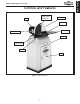
INTRODUCTION Model W1815 (Mfg. Since 10/10) Controls and Features Cast Iron Disc (Sanding Disc Attached) Motor Disc Guard Work Table Miter Gauge On/Off Switch Cabinet Lock Handle (One of Two) Tilt Scale Door Figure 1. Identification.
Model W1815 (Mfg.
Model W1815 (Mfg. Since 10/10) JK89C< D8:?@E<% Unexpected movement during operations greatly increases the risk of injury and loss of control. Verify machines are stable/secure and mobile bases (if used) are locked before starting. =FI:@E> D8:?@E
Model W1815 (Mfg. Since 10/10) SAFETY Additional Safety for Disc Sanders AVOID FINGER INJURIES. Never purposely touch the moving sanding disc. Take care to keep fingers away from sanding disc during operations. If the workpiece is small or difficult to hold, use a workpiece holding fixture. Sanding abrasives can quickly remove large amounts of skin! POSITION TABLE CORRECTLY.
Model W1815 (Mfg. Since 10/10) ELECTRICAL Circuit Requirements This machine must be connected to the correct size and type of power supply circuit, or fire or electrical damage may occur. Read through this section to determine if an adequate power supply circuit is available. If a correct circuit is not available, a qualified electrician MUST install one before you can connect the machine to power.
Model W1815 (Mfg. Since 10/10) Grounding Requirements ELECTRICAL This machine MUST be grounded. In the event of certain types of malfunctions or breakdowns, grounding provides a path of least resistance for electric current to travel—in order to reduce the risk of electric shock. Improper connection of the equipment-grounding wire will increase the risk of electric shock. The wire with green insulation (with/without yellow stripes) is the equipmentgrounding wire.
Model W1815 (Mfg. Since 10/10) SETUP Unpacking This machine has been carefully packaged for safe transportation. If you notice the machine has been damaged during shipping, please contact your authorized Shop Fox dealer immediately. Inventory The following is a description of the main components shipped with the Model W1815. Lay the components out to inventory them. Main Inventory (Figure 3) Qty A. Sander Assembly............................................1 B. Left Side Panel ...........................
Model W1815 (Mfg. Since 10/10) Machine Placement Weight Load Physical Environment Refer to the Machine Specifications for the weight of your machine. Make sure that the surface upon which the machine is placed will bear the weight of the machine, additional equipment that may be installed on the machine, and the heaviest workpiece that will be used. Additionally, consider the weight of the operator and any dynamic loading that may occur when operating the machine.
Model W1815 (Mfg. Since 10/10) Cleaning Machine To prevent corrosion during shipment and storage of your machine, the factory has coated the bare metal surfaces of your machine with a heavy-duty rust prevention compound. If you are unprepared or impatient, this compound can be difficult to remove.
Model W1815 (Mfg. Since 10/10) Assembly Before beginning assembly, refer to the inventory list and group all fasteners with their intended components. Doing this will make assembly easier. When assembling this machine, tighten fasteners using hand tools only.
Model W1815 (Mfg. Since 10/10) 4. Invert the cabinet, thread the (4) hex nuts onto the feet, and install the feet into the base, as shown in Figure 8. 5. Adjust the feet to the same height, tighten the hex nuts against the cabinet base to lock the feet in place, then return the cabinet right side up. Figure 8. Foot installation. 6. With the help of another person, place the sanding unit onto the top of the cabinet, as shown in Figure 9, and fasten it to the cabinet using (4) M8-1.
Model W1815 (Mfg. Since 10/10) Test Run Once assembly is complete, test run your machine to make sure it runs properly and is ready for regular operation. The test run consists of verifying the following: 1) The motor powers up and runs correctly, and 2) the safety disabling mechanism on the switch works correctly. If, during the test run, you cannot easily locate the source of an unusual noise or vibration, stop using the machine immediately, then review Troubleshooting on Page 27.
Model W1815 (Mfg. Since 10/10) OPERATIONS Operation Overview The purpose of this overview is to provide the novice machine operator with a basic understanding of how the machine is used during operation, so they can more easily understand the controls discussed later in this manual. Note: Due to the generic nature of this overview, it is not intended to be an instructional guide for performing actual machine operations.
Model W1815 (Mfg. Since 10/10) Attaching Sandpaper The Model W1815 sander accepts 15" diameter adhesivebacked sanding discs. These are available in a variety of grits. The sanding disc sticks to the surface of the cast iron disc platen, using the pressure-sensitive adhesive backing (PSA). The sandpaper can be replaced without removing either the table or the dust port. OPERATIONS To attach sandpaper, do these steps: 1. DISCONNECT MACHINE FROM POWER! 2.
Model W1815 (Mfg. Since 10/10) Disc Sanding The Model W1815 uses dual-axis miter slot design for increased versatility of workpiece control. Always keep the workpiece on the side of the wheel that is rotating down toward the table. This will keep the workpiece from flying out of your hands if kickback occurs. Figure 13. Example of Y-axis sanding.
Model W1815 (Mfg. Since 10/10) Accessories The following Disc Sander accessories may be available through your local Woodstock International Inc. Dealer. If you do not have a dealer in your area, these products are also available through online dealers. Please call or e-mail Woodstock International Inc. Customer Service to get a current listing of dealers at: 1-800-840-8420 or at sales@woodstockint.com.
Model W1815 (Mfg. Since 10/10) MAINTENANCE Schedule For optimum performance from your machine, follow this maintenance schedule and refer to any specific instructions given in this section. Check for the following conditions and repair or replace when necessary: Daily Check: • Loose mounting bolts. • Worn, loose, or damaged sanding disc. • Worn or damaged power cord. • Any other condition that could hamper the safe operation of this machine.
Model W1815 (Mfg. Since 10/10) SERVICE General This section covers the most common service adjustments or procedures that may need to be made during the life of your machine. If you require additional machine service not included in this section, please contact Woodstock International Technical Support at (360) 734-3482 or send e-mail to: tech-support@shopfox.biz.
Model W1815 (Mfg. Since 10/10) Miter Gauge Calibration At 90˚ the miter gauge should be perpendicular to the face of the wheel when it is mounted in the table slot. If it is not, follow this procedure to recalibrate it. Tools Needed: Machinist's Square...............................................1 Phillips Head Screwdriver......................................1 To calibrate the miter gauge, do these steps: 1. DISCONNECT MACHINE FROM POWER! 2.
Model W1815 (Mfg. Since 10/10) Table Tilt Calibration When the table is perpendicular to the sanding disc, the scale should read 0˚. If not, follow this procedure. Tools Needed: Machinist's Square...............................................1 Phillips Head Screwdriver......................................1 To calibrate the table tilt, do these steps: 1. DISCONNECT MACHINE FROM POWER! 2.
Model W1815 (Mfg. Since 10/10) Electrical Safety Instructions These pages are current at the time of printing. However, in the spirit of improvement, we may make changes to the electrical systems of future machines. Study this diagram carefully. If you notice differences between your machine and these wiring diagrams, call Woodstock International Technical Support at (360) 734-3482. (% J?F:B ?8Q8I;% Working on wiring that is connected to a power source is extremely dangerous.
Model W1815 (Mfg. Since 10/10) Wiring Diagram Regulator Motor Start Capacitor ON/OFF Switch Figure 20. W1815 wiring component locations.
Model W1815 (Mfg. Since 10/10) Troubleshooting This section covers the most common problems and corrections with this type of machine. WARNING! DO NOT make any adjustments until power is disconnected and moving parts have come to a complete stop! PROBLEM POSSIBLE CAUSE corrective action Motor will not start or is 1. Switch disabling key removed. slow to start. 2. Break or short in wiring, loose connections, plug or receptacle is corroded or miswired. 3. Power supply switched off/has incorrect voltage.
Model W1815 (Mfg. Since 10/10) PROBLEM POSSIBLE CAUSE corrective action Sandpaper clogs quickly or 1. Sandpaper grit is too fine for the burns. job. 2. Workpiece is too moist. 3. Sanding depth too aggressive. 4. Paint, varnish, pitch, or other coating is loading up sandpaper. 5. Sanding soft workpiece. 1. Replace with a coarser grit sandpaper. Glossy spots, burning, streaks on workpiece. 1. Use a coarser grit sandpaper. or 1. Sandpaper too fine for the desired finish. 2. Work held still for too long.
Model W1815 (Mfg.
Model W1815 (Mfg. Since 10/10) Machine Labels Safety labels warn about machine hazards and how to prevent machine damage or injury. The owner of this machine MUST maintain the original location and readability of all labels on this machine. If any label is removed or becomes unreadable, REPLACE that label before allowing the machine to enter service again. Contact Woodstock International, Inc. at (360) 734-3482 or www. shopfoxtools.com to order new labels.
Model W1815 (Mfg.
FOLD ALONG DOTTED LINE Place Stamp Here NFF;JKF:B @EK?8D# N8 0/)).
WARRANTY N8II8EKP Nff[jkfZb @ek\ieXk`feXc# @eZ% nXiiXekj Xcc J_fg =fo dXZ_`e\ip kf Y\ ]i\\ f] [\]\Zkj ]ifd nfibdXej_`g Xe[ dXk\i`Xcj ]fi X g\i`f[ f] knf p\Xij ]ifd k_\ [Xk\ f] fi`^`eXc gliZ_Xj\ Yp k_\ fi`^`eXc fne\i% K_`j nXiiXekp [f\j efk Xggcp kf [\]\Zkj [l\ [`i\Zkcp fi `e[`i\Zkcp kf d`jlj\# XYlj\# e\^c`^\eZ\ fi XZZ`[\ekj# cXZb f] dX`ek\eXeZ\# fi i\`dYlij\d\ek f] k_`i[ gXikp \og\ej\j `eZlii\[% Nff[jkfZb @ek\ieXk`feXc# @eZ% n`cc i\gX`i fi i\gcXZ\# Xk `kj \og\ej\ Xe[ Xk `kj fgk`fe# k_\ J_fg =fo dXZ_`e\
=^\] FjVa^in BVX]^cZh VcY Iddah LddYhidX` >ciZgcVi^dcVa! >cX# XVgg^Zh i]djhVcYh d[ egdYjXih YZh^\cZY id bZZi i]Z cZZYh d[ idYVn h lddYldg`Zgh VcY bZiValdg`Zgh# 6h` ndjg YZVaZg VWdji i]ZhZ [^cZ egdYjXih/