MODEL W1668 1 13 ⁄4" Oscillating Drill Press INSTRUCTION MANUAL Phone: 1-800-840-8420 • On-Line Technical Support: tech-support@woodstockint.com COPYRIGHT © 2000 BY WOODSTOCK INTERNATIONAL, INC. WARNING: NO PORTION OF THIS MANUAL MAY BE REPRODUCED IN ANY SHAPE OR FORM WITHOUT THE WRITTEN APPROVAL OF WOODSTOCK INTERNATIONAL, INC.
PAGE 1. 7. MAINTENANCE 6. OPERATIONS 5. ADJUSTMENTS 4. ASSEMBLY 3. SAFETY 2. INTRODUCTION ABOUT YOUR NEW DRILL PRESS ......................................................2 WOODSTOCK SERVICE AND SUPPORT ................................................2 WARRANTY AND RETURNS ..............................................................3 MACHINE SPECIFICATIONS ..............................................................3 SAFETY.....................................................................
INTRODUCTION INTRODUCTION ABOUT YOUR NEW DRILL PRESS This new Shop Fox® Oscillating Drill Press has been specially designed by Woodstock International, Inc. to provide many years of trouble free service. Close attention to detail, ruggedly built parts and a rigid quality control program assure safe and reliable operation. The Shop Fox® Model W1668 is a drill press and oscillating sander in one compact machine. It is capable of a wide variety of drilling and sanding operations.
Woodstock International, Inc. warrants all SHOP FOX® machinery to be free of defects from workmanship and materials for a period of 2 years from the date of original purchase by the original owner. This warranty does not apply to defects due directly or indirectly to misuse, abuse, negligence or accidents, lack of maintenance, or to repair or alterations made or specifically authorized by anyone other than Woodstock International, Inc. Woodstock International, Inc.
SAFETY SAFETY FIRST! READ MANUAL BEFORE OPERATING MACHINE FAILURE TO FOLLOW INSTRUCTIONS BELOW WILL RESULT IN PERSONAL INJURY Indicates an imminently hazardous situation which, if not avoided, WILL result in death or serious injury. Indicates a potentially hazardous situation which, if not avoided, COULD result in death or serious injury. Indicates a potentially hazardous situation which, if not avoided, MAY result in minor or moderate injury. It may also be used to alert against unsafe practices.
11. Disconnect machine when cleaning, adjusting or servicing. 12. Do not force tool. The machine will do a safer and better job at the rate for which it was designed. 13. Use correct tool. Do not force machine or attachment to do a job for which it was not designed. 14. Wear proper apparel. Do not wear loose clothing, neck ties, gloves, jewelry, etc. 16. Use proper extension cord. When using an extension cord, make sure it is in good condition.
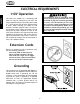
ELECTRICAL REQUIREMENTS SAFETY 110V Operation ® This equipment must be grounded. Verify that any existing electrical outlet and circuit you intend to plug into is actually grounded. If it is not, it will be necessary to run a separate 12 A.W.G. copper grounding wire from the outlet to a known ground. Under no circumstances should the grounding pin from any three-pronged plug be removed. Serious injury may occur. 1 The Shop Fox W1668 13 ⁄4" Oscillating Drill Press can only be operated at 110 volts.
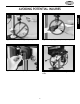
AVOIDING POTENTIAL INJURIES SAFETY Figure 2. Never drill, holding workpiece by hand. Figure 3. Keep fingers away from spinning tool. Fig. 4. Remove Switch Safety Key when not in use. Figure 5. Remove handles when using oscillating mode.
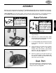
ASSEMBLY ASSEMBLY INSTRUCTIONS Figure 6. Components laid out for identification. The following is a description of the components shipped with the Shop Fox® W1668 Oscillating Drill Press. It is recommended that the components be laid out in a similar fashion to those in Figure 6. This will help in identification before beginning assembly. Should any part be missing, examine the packaging carefully and check under the belt guard.
ASSEMBLY While the main components of the Shop Fox® W1668 Oscillating Drill Press are assembled at the factory, some assembly is required. The following is the recommended sequence best suited for final assembly. TOOLS REQUIRED: You will need a 10mm, 12mm and 14mm open end wrench, a flat tipped screwdriver, a Phillips® screwdriver (not supplied) and a 3mm, 4mm and 5mm Allen® wrench (supplied). Base/Column Do not connect the machine to power at this time.
Table Support 1. Thread the 12mm table lock handle 3 turns into the table support bracket. ASSEMBLY 2. Insert the pinion into the hole on the side of the table support bracket from the inside, starting with the pinion shaft. Figure 9. Align setscrew in crank handle with flat, Figure 10, on pinion shaft and secure using the 3mm Allen® wrench provided. 3. Insert the lock shoe into the table support bracket and secure with setscrews on either side. Figure 11. Figure 9.
Table Support, Cont. 4. Examine the rack and note that the gear teeth extend further on one end than the other. Insert the rack into the table support bracket and align with pocket. The end of the rack where the gear teeth are closest to the end should be positioned down when the support bracket is oriented as in Figure 12. The gear teeth on the rack must also face out. Figure 12. Hold rack in position while installing. 6. Slide the column ring onto the column with the inside bevel in the down position.
HeadStock ASSEMBLY The headstock represents a heavy load. Seek assistance before beginning this step. 1. The bottom of the headstock has a pocket for inserting the column. Position the pocket over the column, as in Figure 15. Allow the headstock to slide down until it stops (approximately 31⁄2"). Figure 15. Align pocket in headstock with column. 2. Align the headstock directly over the foot of the base by using a plumb bob. Lay a measuring tape or ruler across the drill press base and find its center.
Drill Chuck The drill chuck is attached to the drill spindle by means of matched tapers and screw. To mount the drill chuck to the spindle, carefully follow the instructions below: 1. The drill chuck and spindle must be thoroughly cleaned before assembly. It is recommended that mineral spirits be used for this task. Refer to the safety warnings on the container. Failure to clean the mating surfaces may result in separation and wear. DO NOT use a hammer on the drill chuck to seat it onto the spindle.
ADJUSTMENTS Speed Change ADJUSTMENTS Unplug the drill press before changing speeds to avoid accidental start up. Failure to do this may result in serious personal injury. Unplug the drill press before changing speeds. The Oscillating Drill Press has 12 speeds ranging from 250 to 3050 RPM. There is a speed chart located under the belt guard and one on the following page. Refer to the speed chart while reading these instructions. Figure 21. Loosening lock knob 1. Loosen the belt tension lock knob.
More About Speed Change The speed chart above is included to help illustrate belt changes necessary to produce a desired speed. Select the proper speed for the job at hand and find it on the speed chart above. Move the belts to the indicated location on the chart. The belt setting in the example above shows the belt in the #1 spindle pulley position and the belt is in the #7 motor pulley location. This will produce a speed of 1,870 RPM. Spindle Adjustments 1. Loosen the depth collar lock knob.
Oscillating Feature One of the great features of the W1668 Drill Press is its capability for oscillating sanding. The drill press can be converted from drilling operations to sanding operations in just a few steps. 1. Unplug the drill press and remove the spindle handles. 2. Install the round rubber belt onto the top groove in the spindle pulley and the oscillating pulley located between the idler pulley and the spindle pulley. The belt will stretch for this purpose. Figure 22. Figure 26.
Table Adjustments The table can be adjusted to accommodate height of materials to be sanded or drilled. To adjust: 1. Loosen the table support bracket lock knob. Turn the table hand crank to raise or lower the table. Figure 27. 2. The table can be adjusted out of the way so the base of the drill press may be used to support the workpiece for drilling operations only. Loosen the table lock knob and pivot the table to the back side of the column. Figure 28. Figure 27. Use handle to adjust table height. 4.
OPERATIONS Test Run Once assembly is complete and adjustments are done to your satisfaction, you are ready to test run the machine. Always wear safety glasses when operating drill press. Failure to comply may result in serious personal injury. OPERATIONS Make sure the starting switch is off. The paddle is down when off. Make sure all the fasteners and lock handles are tight. Plug in the power cord. Pull the START paddle.
Drill Changes Care must be taken to secure the bit firmly in the drill chuck. When changing bits, proceed as follows: 1. Disconnect the machine from the power source. 2. Open the chuck wide enough to accept a drill bit. 3. Install the bit so the chuck jaws will grab as much of the bit shank as it can. Figure 31. Do not allow the chuck to grab the fluted body of the drill bit. Make sure small drill bits do not get trapped between the edges of two jaws. Figure 31. Installing bit. 4.
MAINTENANCE Table And Base General Tables can be kept rust-free with regular applications of products like Boeshield® T-9. For long term storage you may want to consider products like Kleen Bore's Rust Guardit™. Disconnect power to the machine when performing any maintenance or repairs. Failure to do this may result in serious personal injury. Lubrication Since all bearings are shielded and permanently lubricated, simply leave them alone until they need to be replaced. Do not lubricate them.
CLOSURE The following pages contain general machine data, parts diagrams/lists and warranty/return information for your Shop Fox® Model W1668 Drill Press. We recommend you keep this manual for complete information regarding Woodstock International, Inc.’s warranty and return policy. Should a problem arise, we recommend that you keep proof of purchase with your manual.
PARTS
PART # 01 02 03 04 06 07 08 09 10 11 12 13 14 15 16 17 18 19 20 21 22 23 24 25 26 27 28 29 30 31 32 33 34 35 36 37 38 38C 39 40 41 42 43 44 45 46 48 49 50 51 52 53 54 X1668001 X1668002 X1668003 X1668004 XPB32M X1668007 X1668008 XPSS01M X1668010 X1668011 X1668012 X1668013 X1668014 X1668015 X1668016 XPSS01M XPSS22M X1668019 X1668020 XPS33M X1668022 XPN02M X1668016 X1668025 X1668026 X1668027 XPN01M X1668029 X1668030 X1668031 XPRP07M X1668033 X1668034 X1668035 X1668036 X1668037 X1668038 X1668038C XPSS16M XPSS
NOTES: -24-
WARRANTY CARD Name __________________________________________________________________________________________ Street __________________________________________________________________________________________ City ____________________________________________________________________State________Zip_________ Phone Number_______________________E-Mail_______________________FAX________________________ MODEL # ________________________________________________________________________________________ The following in
FOLD ALONG DOTTED LINE Place Stamp Here WOODSTOCK INTERNATIONAL, INC. P.O.