MODEL W1679 6" Jointer INSTRUCTION MANUAL Phone: 1-360-734-3482 • On-Line Technical Support: tech-support@woodstockint.com COPYRIGHT © JULY, 2002 BY WOODSTOCK INTERNATIONAL, INC. WARNING: NO PORTION OF THIS MANUAL MAY BE REPRODUCED IN ANY SHAPE OR FORM WITHOUT THE WRITTEN APPROVAL OF WOODSTOCK INTERNATIONAL, INC.
WARNING Some dust created by power sanding, sawing, grinding, drilling, and other construction activities contains chemicals known to the State of California to cause cancer, birth defects or other reproductive harm. Some examples of these chemicals are: • Lead from lead-based paints. • Crystalline silica from bricks, cement, and other masonry products. • Arsenic and chromium from chemically treated lumber. Your risk from these exposures varies, depending on how often you do this type of work.
1. PARTS USE THE QUICK GUIDE PAGE LABELS TO SEARCH OUT INFORMATION FAST! MAINTENANCE 6. OPERATIONS 5. ADJUSTMENTS 4. ASSEMBLY 3. SAFETY 2. PAGE INTRODUCTION ..............................................................................................2 About Your New Jointer ............................................................................2 Woodstock Service And Support ..................................................................2 Warranty And Returns...........................
INTRODUCTION INTRODUCTION About Your New Jointer Your new Shop Fox® Jointer has been specially designed to provide many years of trouble-free service. Close attention to detail, ruggedly built parts and a rigid quality control program assure safe and reliable operation. The Model W1679 is capable of a wide variety of surface jointing/planing, edge jointing, beveling and rabetting operations.
Woodstock International, Inc. warrants all SHOP FOX® machinery to be free of defects from workmanship and materials for a period of 2 years from the date of original purchase by the original owner. This warranty does not apply to defects due directly or indirectly to misuse, abuse, negligence or accidents, lack of maintenance, or to repairs or alterations made or specifically authorized by anyone other than Woodstock International, Inc. Woodstock International, Inc.
SAFETY SAFETY READ MANUAL BEFORE OPERATING MACHINE. FAILURE TO FOLLOW INSTRUCTIONS BELOW WILL RESULT IN PERSONAL INJURY. Indicates an imminently hazardous situation which, if not avoided, WILL result in death or serious injury. Indicates a potentially hazardous situation which, if not avoided, COULD result in death or serious injury. Indicates a potentially hazardous situation which, if not avoided, MAY result in minor or moderate injury, or MAY result in property damage.
12. Do not force the machine. The machine will do a safer and better job at the rate for which it was designed. 13. Use the correct tool. Do not force the tool or attachment to do a job for which it was not designed. 15. Remove all adjusting keys and wrenches. Before turning the machine on, make it a habit to check that all adjusting keys and wrenches have been removed. 16. Use proper extension cord. Examine the extension cord to ensure it is in good condition.
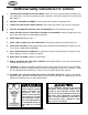
SAFETY Additional Safety Instructions For Jointers 1. JOINTING SAFETY BEGINS WITH YOUR LUMBER. Inspect your stock carefully before you feed it over the cutterhead. If you have any doubts about the stability or structural integrity of your stock, DO NOT JOINT IT! 2. MAINTAIN THE PROPER ALIGNMENT of the outfeed table with the cutterhead knife. 3. ALWAYS USE PUSH BLOCKS WHEN JOINTING. Never allow your hands to get near the cutterhead. 4.
Avoiding Potential Injuries SAFETY Figure 1. Correct operator and workpiece position, guard is in place, and push blocks are being used. Figure 2. Never surface plane without push blocks! Figure 3. Never stand directly behind the workpiece! Figure 4. Never plane/edge-joint with the guard removed! Figure 5.
SAFETY 110V Operation Do not remove the grounding pin from any plug and always make sure all wiring to the machine is grounded before operating. Any electrical outlet and circuit that you plug your machine into must be grounded. Serious injury may occur if this warning is ignored! The Shop Fox® W1679 is prewired for 110 volts. The motor supplied with your new machine is rated at 1 HP and will draw approximately 14 amps.
220V Operation The Shop Fox® W1679 can also be operated at 220 volts. To do this, you must purchase the optional 220V magnetic switch that is shown in the parts diagram at the back of this manual. Also, you will need a NEMA-style 6-15 plug and outlet. The motor supplied with your new machine is rated at 1 HP and will draw approximately 7 amps during 220 volt operation. When choosing an outlet for this machine, consider using one with a 10 amp circuit breaker or fuse.
ASSEMBLY INSTRUCTIONS Unpacking Read and understand this entire instruction manual before performing any operations with your machine. Otherwise, serious personal injury may occur if safety and operational information is not understood and followed. Do not risk your safety by not reading! ASSEMBLY The Model W1679 has been carefully packaged for safe transporting.
Shop Preparation Floor Load: Your Model W1679 represents a large weight load in a small footprint. While most commercial floors are suitable for this jointer, some residential floors may require additional bracing to support both machine and operator. • Working Clearances: Consider existing and anticipated needs, size of material to be processed through each machine, and space for auxiliary stands, work tables or other machinery when establishing a location for your machine.
Beginning Make sure that your machine is unplugged during all assembly procedures! If this warning is ignored, serious personal injury may occur. ASSEMBLY Although the main components of the Shop Fox® W1679 are assembled at the factory, some assembly is required. The following series of instructions are the recommended sequence best suited for final assembly. Mounting Jointer 1. Determine the best place for the jointer in your shop and place the cabinet stand in that location. 2.
4. Halfway between the two pulleys, lightly squeeze each side of the belt together to check the tension. Belt too loose? If each side of the belt squeezes toward each other more than 1⁄2", increase the tension by repeating steps 2 and 3. Figure 12. Pulley and V-belt alignment. 5. Check the V-belt pulley alignment. Minor adjustments may be made by loosening the pulley setscrew and sliding the pulley along the shaft. See Figure 12 for details.
4. 5. Place the 1⁄2" flat washer over the lock knob and install the special nut from underneath the fence support as shown in Figure 15. Lock Knob Make sure the splines on the special nut protrude into the adjustment slot, then insert the knob through the fence housing and thread the knob into the special nut. Tilt Knob Special Nut ASSEMBLY Cutterhead Guard 1. 2. Remove the setscrew from the slot in the end of the cutterhead guard shaft. Figure 15. Installing lock knob and special nut.
Belt Guard Attach the belt cover to the cabinet stand with the 5⁄16"-18 x 21⁄2" hex bolt as shown in Figure 18. Figure 18. Attach belt guard to stand with the hex bolt. Knife Gauge The knife gauge consists of a steel rod, two adjuster arms and two E-clips. To assemble the knife gauge: 1. Insert the steel rod through each adjuster arm. 2. Snap the E-clips into the grooves at the ends of the steel rod so your assembly looks like the knife gauge shown in Figure 19. Figure 19. Knife setting gauge.
ADJUSTMENTS Checking Knives Make sure that your machine is unplugged during any adjustment procedures! If this warning is ignored, serious personal injury may occur. The cutterhead knives have been set at the factory and should require no adjustments when you first receive your jointer. However, it is always a good idea to verify the accuracy of any adjustments that will affect your finished product.
Adjusting Knives The knives in the Model W1679 come from the factory with jack screws installed. Springs are also included as an option for knife adjustments, depending on your preference. Figure 22 shows an illustration of the cutterhead components. The knife position should be as precise as possible in the cutterhead. All knives should be within .002" from one end to the other and within .002" from one knife to another. To adjust the knives: Figure 22. Understanding cutterhead assembly.
Table Gibs The table gibs allow you to control how easy the table moves up or down and control the precision of the table movement along the dovetail ways. Since the table gibs are factory set, they do not need to be adjusted unless the table is too loose or too tight when moving along the dovetail ways. (Always make sure the table lock is released before determining whether the table travel is too loose or too tight.) To adjust the table gibs: 1. Unplug the jointer! 2.
Figure 27. Straightedge centered on outfeed table and even with knife at top dead center. 5. Place a good quality straightedge across the length of the outfeed table and just over the cutterhead as shown in Figure 27. (This adjustment works best if the straightedge is placed in the center of the outfeed table.) 6. Using the handwheel under the outfeed table, raise or lower the outfeed table until the straightedge barely touches the edge of the knife. 7.
Fence Stops 45˚L Stop bolts on the back of the fence (shown in Figure 30) allow you to quickly and accurately move the fence to 90˚, 45˚ R (to the right) and 45˚ L (to the left). The position of these stops must be checked and possibly adjusted before they are used for the first time. 90˚ Fence-Tilt Lock Knob 45˚R The fence stops are simple hex bolts (a nut for 45˚ L) that thread in or out to match the depth required. Each fence stop has a jam nut to lock the stops in place for repeatable accuracy.
OPERATIONS Starting Jointer Always wear safety glasses during operations. Serious injury may occur if this is warning is ignored! Once assembly is complete and adjustments have been made, the jointer is ready for a test run. The purpose of a test run is to identify any unusual noises and vibrations, as well as to confirm the machine is performing as intended. Always keep loose clothing and long hair secured and away from moving parts.
Operation Musts • Never allow hands or push blocks to come within 4" of the cutterhead while it is moving. • Carefully inspect any lumber that you plan to run through the jointer. Some defects such as moderate twisting, loose knots or severe cracks may make the stock unusable. • Only use clean stock. See Figure 33. Remove all dirt, nails, staples, imbedded gravel, etc. from any lumber you plan on using. A hidden nail in a workpiece will instantly damage the sharp edges of the knives.
Surface Planing One of the most common operations on the jointer is surface planing. Surface planing produces one flat surface on a piece of stock as shown in Figure 35. After being surface planed, the stock is usually run through a thickness planer so the board thickness is consistent from one end to the other. Figure 36 shows an example of an operator using the jointer to surface plane a piece of wood stock.
Edge Jointing Edge jointing is passing the workpiece over the jointer on its edge as shown in Figure 37. This process makes the edges of a workpiece perfectly flat. Stock must be edge jointed on the concave side. The convex side should then be cut straight with a table saw. This process is commonly used to prepare the workpiece to be glued-up as part of a larger assembly or to simply salvage warped stock. Portion Removed With Jointer Figure 38 shows an example of an operator edge jointing.
Bevel Cutting Bevel cutting is very similar to edge jointing, but done with the fence tilted to a specific angle in order to produce an angled edge as shown in Figure 39. Usually bevel cuts are made on two boards that will be joined together at a corner. For bevel cuts, the model W1679 has preset stops at 45˚ L and 45˚ R. If a different angle is desired, use a bevel gauge to set the fence, then lock it in position.
Rabbet Cutting Rabbet Cut Rabbet cutting recesses a section of a workpiece edge to create a strong but simple joint. Figure 41 illustrates a basic rabbet cut and two common joints. Figure 42 shows an operator performing a rabbet cut. Notice that the fence is positioned close to the edge of the table. The operator’s body is not directly in line with the stock and he maintains a stable hand position while keeping the board firmly on the table and against the fence.
MAINTENANCE General Make sure that your machine is unplugged during all maintenance procedures! If this warning is ignored, serious personal injury may occur. Regular periodic maintenance on your Model W1679 will ensure its optimum performance. Make a habit of inspecting your machine each time you use it. Check for the following conditions and repair or replace when necessary. Always wear safety glasses to prevent serious personal injury! 1. Loose mounting bolts. 2. Worn switch. 3.
Lubrication Since all bearings are sealed and permanently lubricated, simply leave them alone until they need to be replaced. Do not lubricate them. For the moving mechanisms on the fence assembly, an occasional application of light machine oil is all that is necessary. Before applying lubricant, wipe the fence clean. Lubricate the pivot points and move the fence back and forth as shown in Figure 44. Your goal is to achieve adequate lubrication. Too much lubrication will attract dirt and sawdust. Figure 44.
Troubleshooting SYMPTOM Motor will not start and fuses or POSSIBLE REASON 1. Short circuit in line cord or plug. breakers blow. HOW TO REMEDY 1. Inspect cord or plug for damaged insulation and shorted wires. 2. Short circuit in motor or loose con- 2. Inspect all connections on motor for loose or shorted ternections. minals or worn insulation. 3. Incorrect fuses or circuit breakers in 3. Replace with correct fuses or circuit breakers. power line. Motor will not start. 1. Voltage too low. 1.
Troubleshooting POSSIBLE REASON SYMPTOM HOW TO REMEDY 1. Grain direction incorrect or knots in 1. Feed workpiece with the grain. Inspect stock for knots or Chipping occurs on workpiece. workpiece. try again with different stock. 2. Dull knives. 2. Replace or sharpen knives. 3. Too fast of a feed rate. 3. Feed the workpiece at a slower rate. 4. Too deep of cut. 4. Decrease depth of cut. 1. Wood may have high moisture con- 1. Allow wood to dry. Grain is fuzzy after jointing. tent.
MAINTENANCE
CLOSURE We recommend you keep this manual for complete information regarding Woodstock International, Inc.’s warranty and return policy. Should a problem arise, we recommend that you keep your proof of purchase with your manual. If you need additional technical information relating to this machine, or if you need general assistance or replacement parts, please contact the Service Department at 1-360-734-3482 or email: tech-support@woodstockint.com.
48 29 30 1 16 14 38 11 15 35 12 43 36 39 13 37 34 19 24 6 1 28 5 1 4 10 3 1 25 24 27 33 8 32 42 9 31 50 7 21 51 (optional 220V) 26 44 46 2 18 40B 23 22 53 49 40 47 40A 45 52 1 54 18 PARTS 17 41 -33-
-34- 104 PARTS 116 101 111 124 115 109 101 131 108 131 111 130 103 119 132 121 126 112 127 114 129 105 123 106 120 122 117 113 112 102 128 110 107 118 125
REF 1 2 3 4 5 6 7 8 9 10 11 12 13 14 15 16 17 18 19 20 21 22 23 24 25 26 27 28 29 30 31 32 33 34 35 PART # XPW07 XPB21 X1679003 XPVA36 XPK12M XPB03 X1679007 X1679008 XPN08 XPWR810 X1679011 X1679012 X1679013 XPS01 X1679015 XPWRCRD110S X1679017 XPN07 X1679019 X1679020 XPS08 X1679022 XPHTEK10 XPN02 XPCB01 XPW02 XPSS03 X1679028 XPB32 XPWRCRD110L 40A X1679040A 40B X1679040B 41 42 XPW03 X1679042 36 37 38 39 REF FLAT WASHER 5⁄16" HEX BOLT 3⁄8"-16 x 3⁄4" MOTOR PULLEY V-BELT A-36 KEY 5 x 5 x 30L HEX
216 241 214 227 240 240 250 204 249 224 208 215 242 225 230 205 231 220 245 206 234 243 212 232 219 233 207 246 222 209 221 203 248 213 229 201 226 217 228 204 239 238 222 219 244 212 210 206 211 248 202 235 246 236 205 230 233 246 231 PARTS 245 -36- 237 225 220 224 249 250 218
316 315 301 311 306 307 314 310 303 310 312 302 304 305 309 313 317 317 303 312 304 PARTS -37-
REF X1679001 X1679002 XPSS01 X1679004 XPSS11 X1679006 XPW07 X1679008 X1679009 X1679010 X1679011 XPSB03 X1679013 X1679014 XPW02 X1679016 XPS23 X1679018 XPW07 XPS01 XPSS31M XPB57 W1400 X1679024 XPN02 X1679226 X1679227 X1679228 XPN02 X1679230 X1679231 X1679232 X1679233 X1679234 DESCRIPTION REF 235 236 237 238 239 240 241 242 243 244 245 246 247 248 249 250 301 302 303 304 305 306 307 308 309 310 311 312 313 314 315 316 317 INFEED TABLE GIB SETSCREW 5⁄16"-18 x 1" TABLE ADJUST ROD SETSCREW 1⁄4"-20 x 1⁄4" LE
WARRANTY CARD Name __________________________________________________________________________________________ Street __________________________________________________________________________________________ City ____________________________________________________________________State________Zip_________ Phone Number_______________________E-Mail_________________________________FAX___________________ MODEL #______________________________ Serial #___________________________________________________ The follow
FOLD ALONG DOTTED LINE Place Stamp Here WOODSTOCK INTERNATIONAL, INC. P.O.