
International, Inc. Planer User Manual
-36-
N(/()Fne\ijDXelXcD]^%j`eZ\*&'0
J<IM@:<
The feed rollers must be aligned correctly with the table
to maintain a smooth and straight feed.
KfZ_\Zbk_\]\\[ifcc\i$kf$kXYc\Xc`^ed\ek#[fk_\j\
jk\gj1
(. DISCONNECT THE PLANER/MOULDER FROM POWER!
). Remove the chip deflector lock pin, and set the chip
deflector aside.
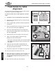
*. Refer to =`^li\54, and make a wooden gauge block
as outlined.
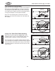
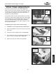
+. Place the finished block on the table, directly under
one end of the infeed roller (=`^li\55).
,. Lower the cutterhead housing so the infeed roller
barely touches the gauge block on the lowest end of
the roller (=`^li\55).
-. Slide the block over to the other end of the roller.
.. Using a set of feeler gauges, measure the gap
between the roller and the block.
—If the gap is more than 0.005", then proceed to Step
8 and adjust the swing arm lower so the gap is less
than 0.005".
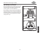
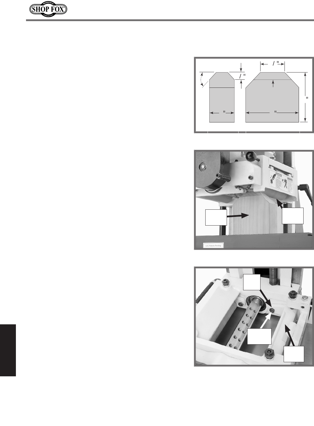
/. Loosen the cap screw shown in =`^li\56, then
rotate the cam nut until the swing arm lowers and
the roller just touches the block.
0. Remove the gauge block and retighten the cap screw.
('. Check and adjust the outfeed roller next.
((. When both rollers are adjusted, check and adjust the
feed roller height and spring tension as outlined in
the Feed Roller Height and Spring Tension section
on Page 21.
(). When finished, reinstall the chip deflector.
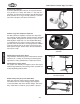
=\\[Ifcc\i$kf$KXYc\
8c`^ed\ek
=`^li\55.Gauge block.
=`^li\56.Feed roller adjustment.
Cam
Nut
Cap
Screw
Gauge
Block
Feed
Roller
=`^li\54.Gauge block plans.
45°
2
4
4
1
1
2
1
2
Grain
Direction
Side View
Front View
Swing
Arm