M O D EL PORTI-S C3 0 (P O R TAB L E P R I N TE R ) WO O S I M S YS TE M I n c . # 5 0 1 , D a er un g Tec h n o t o wn 3 t h , 4 4 8 , G a s a n -D o n g, GeumCh un -Ku, S eo ul , Ko r ea Te l : + 8 2 -2 -2 1 0 7 -3 7 0 0 F a x : + 8 2 -2 -2 1 0 7 -3 7 0 7 U R L h t t p://www. wo o s im. c o m A l l s pec if ic at io n s ar e s u bj ec t ed t o c h an g e wit h o u t n o t ic e ht t p: / / www. woosi m.
C o pyr i g h t Porti-SC30 Portable printer user’s manual. Copyright ⓒ2002 by Woosim System Inc. All rights reserved. The information contained in this manual is the property of Woosim System Inc. and may not be reproduced in whole or in part without the prior written permission of Woosim System Inc. Tr a d ema r k a registered trademark of Woosim System Inc. All other trademark are the properties of their respective companies.
? I n t r o d u c t io n The Porti-SC30 is the ideal solution for Mobile banking system , Retail, point of sales, Credit card Transaction, other traveling and mobile computing etc. The general features of Porti-SC30 printer are as follows: ? Pocket size(75.5 * 112 * 35mm) ? Light weight(340g) for true mobility. ? Very silent printing thru direct thermal printing method. ? High speed(50mm/sec) ? High resolution(203dpi : 8dots/mm). ? Magnetic Stripe Reader included. ? Easier paper loading by CLAMSHELL design.
? O p e r a t in g P r e c a u t io n s Please follow the precautions below to enjoy and maintain the full performance of the printer. ? Using the Printer ● Be careful not to drop or bump the printer on a hard surface. ● Do not install the printer in direct sunlight or such areas.
CO N TEN TS 1 . O u t l in e ……………………………………………………….. 7 1 .1 . Mo d el c l as s if ic at io n s ………………………….. 7 1 .2 . S pec if ic at io n s ……………………………………… 8 2 . S e t t in g u p t h e pr in t e r ………………………………… 9 2 .1 . U n pac k in g ……………………………………………. 9 2 .2 . Ou t er appear an c es an d par t s n ame ……… 1 0 2 .3 . In s t al l in g o r r epl ac in g t h e paper r o l l … 1 2 2 .4 . Po wer c o n n ec t io n ……………………………….. 1 4 2 .4 .1 . S pec if ied po wer s u ppl y ……………… 1 4 2 .4 .2 .
. P r in t C o n t r o l F u n c t io n ………………………………..2 4 6 .1 . Pr in t c o mman d s …………………………………….2 6 6 .2 . L in e s pac in g c o mman d s ………………………….2 8 6 .3 . Ch ar ac t er s c o mman d s …………………………..2 9 6 .4 . Pan el bu t t o n c o mman d s ………………………..3 6 6 .5 . Pr in t po s it io n c o mman d s ……………………….3 7 6 .6 . B it -Imag e c o mman d s ………………………………5 0 6 .7 . S t at u s c o mman d s ………………………………….5 5 6 .8 . B ar c o d e c o mman d s ……………………………….5 6 6 .9 .
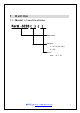
1 O u t l in e 1 .1 . M o d e l c l a s s if ic at io n s Porti –SC30 ( ) ( ) Model name Interface S: Ser i al ( RS- 232C) U: USB Power None : DC 7. 4V ht t p: / / www. woosi m.
1 .2 . S pe c if ic a t io n s Printing method Direct thermal line printing Characters per line 40cpl Character size 9 * 24dots, 16 * 24dots (Korean characters) Resolution 203dpi, 8dots/mm Print width 2-inch (48mm, 384dots) Printing speed 50mm / sec Dimensions 75.5 * 112 * 35 mm (Standard model) Weight 224g (Including battery & roll paper) Interface Serial(RS-232C) or USB, IrDA Ver1.
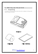
2 S et t in g u p t h e pr in t er 2 .1 . U n pa c k in g Your printer box should include these items. If any items are damaged or missing, please contact your dealer for assistance. PORTI_SC30 ROLL PAPER USER’ S MANUAL ht t p: / / www. woosi m.
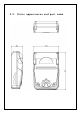
2 .2 . 2 .3 . O u t e r a ppe a r a n c e s a n d pa r t n a me D ime n s io n s ht t p: / / www. woosi m.
ht t p: / / www. woosi m.
2 . 3 . I n s t a l l in g o r r e pl a c in g t h e pa pe r r o l l Note : Be sure to use paper rolls that meet the specifications. Do not use paper rolls that have the paper glued to the core because the printer cannot detect the paper end correctly. 1. Make sure that the printer is not receiving data; otherwise, data may be lost. 2. Open the paper roll cover by applying your finger on both side of printer, push it up when the lock is released as shown in the drawing. 3.
5, Be sure to note the correct direction that the paper comes off the roll. 6, Pull out a small amount of paper and then close the cover, as shown. 7. Tear off the paper as shown. ht t p: / / www. woosi m.
2 . 4 . P o we r c o n n e c t io n 2 .4 .1 . S pec if ied po wer s u ppl y The following specifications is requested for Power supply. VP : DC 7.4V St andby 80mA and Max 2A ( Standard model ) Avoid using power supply which its power capacity of power current is extremely high. 2 .4 .2 . In s t al l at io n / Remo v e t h e bat t er y pac k NOTE : ● Before installing or removing the battery pack, turn the Printer power off.
- Insert the Battery Cover with pushing in the direction of the arrow. ② To remove battery pack, proceed the above order reverse. ht t p: / / www. woosi m.
2 . 5 . S e t t in g o pe r a t io n mo d e 1. Press the MODE Button until the Error Lamp twinkles 5 times 2. Change the mode and option using the MODE Button according to the mode Code(Table1) ?? FEED button : use for changing MODE status. (Power Lamp ) ?? MODE button : use for changing OPTION status.
? Press FEED Button one time, Power Lamp twinkles 3 times and Error Lamp twinkles 2 times ? Press MODE Button one time, Error Lamp twinkles one time (The Data Bit has set to 7 data bit) ? Press FEED Button one time, Power Lamp twinkles 4 times and Error Lamp twinkles 1 time.
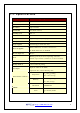
C h a n g e M od e Comunication Port Baud Rate Data Bi t Parity Bit Density Not used POWER Lamp ( G r e e n) 1 2 3 4 5 6 MODE Lamp Option ( R e d) 1 RS-232C or USB 2 Protocol IrDA 3 Standard IrDA 1 1200 bps 2 2400 bps 3 4800 bps 4 9600 bps 5 19200 bps 6 38400 bps 7 57600 bps 8 9600 bps 1 7 Data bit 2 8 Data bit 1 No Parity 2 Even Parity 3 Odd Parity 1 Density Low 2 Density Medium 3 Density High 1 Not used 2 Not used < Table 1> ht t p: / / www.
3 I n t er f a c e The Por t i _SC30 pr i nt er has an RS232 ser i al , or USB i nt er f ace and i s connect ed by means of a 4 pi n mi ni USB socket . I n t he f ol l owi ng t abl e, t he si gnal s pr esent on t he Mi ni USB socket ar e l i st ed: ① Serial Pin No. Name Direction Function 1 TxD Out put Tr ansmi t Dat a 2 RxD I nput Recei ve Dat a 3 CTX - - 4 GND - Gr ound ② USB - Standard Type- Pin No. Name 1 VCC 2 DATA “- “ 3 DATA “+” 4 Gr ound ht t p: / / www. woosi m.
4 U s in g t h e pr in t er 4 . 1 . C o n t r o l pa n e l ? Button - FEED Button : Press the FEED button once to advance paper one line. You can also hold down the FEED button to feed paper continuously. - MODE Button : MODE Button is for use to change communication mode. (Refer to 2 . 5 .
4 . 2 . Th e s e l f t e s t The self-test checks whether the printer has any problems. If the printer does not function properly, contact your dealer. The self-test checks the following; 1. Make sure paper roll has been installed properly. 2. Turn on the power while holding down the FEED button. The self-test begins. 3. The self-test prints the current printer status, which provides the control ROM version and the communication method setting. 4.
5 Co n s u mabl e Par t s 5 . 1 R e c o mme n d e d pa pe r Type : Thermal Paper Paper width : 57mm Paper thickness : 65±5 Mm Outer diameter : Ø30mm or less Recording side : Outside of roll Cautions 1. Do not paste the paper to the core. And the roll paper which has Near end mark printing on its near end is recommended. 2. Chemicals or oil may change the color of paper, or printed Characters may fade. 3. Change of paper color starts from approx 70 C.
5 . 2 P r in t in g po s it io n ht t p: / / www. woosi m.
6 . Pr in t Co n t r o l Fu n c t io n ● Supported Commands List Command Name Function Type Page HT Horizontal tab Print position 40 LF Print and line feed Print 26 FF Print and return to standard mode Print 27 Real-time status transmission Status 35 EOT Cancel car d r eader mode.
Command Name Function Type Page ESC T Select print direction in page mode Print position 46 ESC W Set printing area in page mode Print position 44 ESC X 4 Define user-defined bit-image Bit image 53 ESC \ Set relative print position Print position 38 ESC Z Print 2D barcode Barcode 59 ESC a Select justification Print position 39 ESC c 5 Enable/disable panel buttons Panel button 36 ESC d Print and feed n lines Print 27 ESC i Partial cut (One point center uncut) Mechanism c
6 . 1 . P r in t C o mma n d The PORTI-Series supports the following commands for printing character and advancing paper: Co mmand N ame LF Print and line feed ESC J Print and feed paper ESC d Print and feed n lines FF Print and return to standard mode(in page mode) ESC FF Print data in page mode LF [Name] Print and line feed [Format] ASCII LF HEX 0A Decimal 10 [Description] Print the data in the print buffer and feeds one line based on the current line spacing.
ESC d n [Name] Print and feed n lines [Format] ASCII ESC d n HEX 1B 64 n Decimal 27 100 n [Range] 0 ≤ n ≤ 255 [Description] Prints the data in the print buffer and feeds n lines. [Note] 1) This command sets the print starting position to the beginning of the line. 2) This command does not affect the line spacing set by ESC 2 or ESC 3. [Reference] ESC 2, ESC 3 FF [Name] Print and return to standard mode in page mode.
6 . 2 . L in e S pa c in g C o mma n d The PORTI-Series supports the following commands for setting line spacing. These commands only set the line spacing; they do not actually advance the paper. The line spacing set using these commands affects the results of LF and ESC d and paper feeding by using the FEED button.
3) The GS P command can change the horizontal (and vertical) motion unit. However, the value cannot be less than the minimum vertical movement amount, and it must be in even units of the minimum vertical movement amount. 4) In standard mode, the vertical motion unit (y) i s used.
ESC SP n [Name] Set right-side character spacing. [Format] ASCII ESC SP n HEX 1B 20 n Decimal 27 32 n [Range] 0 ≤ n ≤ 255 [Description] Sets the character spacing for the right side of the character to [n x horizontal or vertical motion units] inches. [Note] 1) The right side character spacing for double-width mode is twice the normal value. When characters are enlarged, the right side character spacing is n times normal value. 2) This command sets values independently in each mode.
n [Default] Character set n Character set 0 U. S. A 6 Sweden 1 Fr ance 7 I t al y 2 Ger many 8 Spai n 3 U. K 9 Nor way 4 Denmar k 10 Denmar k I I n=0 ESC ! n [Name] Select print mode. [Format] ASCII ESC ! n HEX 1B 21 n Decimal 27 33 n [Range] 0 ≤ n ≤ 255 [Description] Select print mode(s) using n as follows,.
[Note] 1) When both double-height and double-width modes are selected, quadruple size characters are printed. 2) The printer can underline all characters, but can not underline the space set by HT. 3) The thickness of the underline is that selected by ESC -, regardless of the character size. 4) When some characters in a line are double or mode height, all the characters on the line are aligned at the baseline. 5) ESC – can also turn on or off underline mode.
following data is not underlined, and the underline thickness set before the mode is turned off does not change. The default underline thickness is 1 dot. 4) Changing the character size does not affect the current underline thickness. 5) Underline mode can also be turned on or off by using ESC !. Note, however, that the last received command is effective. [Default] n=0 [Reference] ESC ! ESC E n [Name] Turn emphasized mode On/Off.
[Note] 1) Only the lowest significant bit of n is valid. 2) This command is enabled only when processed at the beginning of a line in standard mode. 3) When this command is input in page mode, the printer performs only internal flag operations. 4) This command does not affect printing in page mode. 5) In upside-down printing mode, the printer rotates the line to be printed by 180 degree and then prints it.
Hex Decimal W i d t h Hex Decimal Height 00 0 1 ( nor mal ) 00 0 1 ( nor mal ) 01 1 2 ( doubl e wi dt h) 10 16 2 ( doubl e hei ght ) 02 2 3 20 32 3 03 3 4 30 48 4 04 4 5 40 64 5 05 5 6 50 80 6 06 6 7 60 96 7 07 7 8 70 112 8 Character Height Selection Character Width Selection [Notes] 1) This command is all characters effective 2) If n is outside of the defined range, this command is ignored.
[Notes] 1) When the LSB is 0, white/black reverse printing mode is turned on. 2) When the LSB is 1, white/black reverse printing mode is turned off. 3) Only the lowest bit of n is valid. 4) This command is available for built in characters and user defined characters. 5) When white/black reverse printing mode is on, it also applied to character spacing set by ESC SP. 6) This command does not affect the space between lines. 7) White/black reverse mode has a higher priority than underline mode.
2) When the panel buttons are disabled, none of them are usable when the printer cover is closed. 3) In this printer, the panel buttons is the FEED button. 4) In the macro ready mode, the FEED button are enabled regardless of the settings of this command; however, the paper cannot be fed by using these buttons. [Default] n=0 6 . 5 .
[Description] Set the distance from the beginning of the line to the position at which subsequent characters are to be printed. [Notes] 1) The distance from the beginning of the line to the print position is [(nL + nH x 256) x (vertical or horizontal motion unit)] inches. 2) Setting outside the specified printable area are ignored. 3) The horizontal and vertical motion unit are specified by GS P. 4) The GS P command can change the horizontal (and vertical) motion unit.
2) Any setting that exceeds the printable are is ignored 3) When pitch N is specified to the right; nL + nH x 256 = N When pitch N is specified to the left (the negative direction), use the complement of 65536. 4) The print starting position moves from the current position to [N x horizontal or vertical motion unit)] 5) The horizontal and vertical motion unit are specified by GS P. 6) The GS P command can change the horizontal (and vertical) motion unit.
[Notes] 1) The command is enabled only when processed at the beginning of the line in standard mode. 2) If this command is input in page mode, the printer performs only internal flag operations. 3) This command has no effect in page mode. 4) This command executes justification in the printing area. 5) This command justifies the space area according to HT, ESC $ or ESC \ [Default] n=0 [Example] HT [Name] Horizontal Tab [Format] ASCII HT HEX 09 Decimal 9 [Description] Moves the print position t
ESC D n1…nk NUL [Name] Set horizontal tab positions. [Format] ASCII ESC D n1…nk NUL HEX 1B 44 n1…nk 00 Decimal 27 68 n1…nk 0 [Range] 1 <= n <= 255 0 <= k <=32 [Description] Set horizontal tab position [Notes] 1) n specifies the column number for setting a horizontal tab position from the beginning of the line. 2) k indicates the total number of horizontal tab positions to be set.
GS L nL nH [Name] Set left margin. [Format] ASCII GS L nL nH HEX 1D 4C nL nH Decimal 29 76 nL nH [Range] 0 ≤ nL ≤ 255, 0 ≤ nH ≤ 255 [Description] Set the left margin using nL and nH. [Notes]1) The left margin is set to [(nL+nHx256)] x (horizontal motion unit) inches. 2) This command is effective only processed at the beginning of the line in standard mode. 3) If this command is input in page mode, the printer performs only internal flag operations.
GS W nL nH [Name] Set printing area width [Format] ASCII GS W nL nH HEX 1D 57 nL nH Decimal 29 87 nL nH [Range] 0 ≤ nL ≤ 255, 0 ≤ nH ≤ 255 [Description] Sets the printing area width to the area specified by nL and nH. [Notes] 1) The printing area width is set to [(nL+nHx256)] x horizontal motion unit inches. 2) This command is effective only processed at the beginning of the line. 3) In page mode, the printer performs only internal flag operations.
If the printing area width cannot be extended sufficiently, the right space is reduced. 9) If the width set for the printing area is less than one line in vertical, the following processing is performed only on the line in question when data other than character data(e.g., bit image, user defined bit image) is developed: The printing area width is extended to the right to accommodate one line in vertical for the bit image within the printable area.
dy = [(dyL + dyH * 256)] * (vertical motion unit) The printing area is set as shown in the figure below. [Note] 1) If this commands is input in standard mode, the printer executes only internal flag operation. This command does not affect printing in standard mode. 2) If the horizontal or vertical starting position is set outside the printable area, the printer stops command processing and processes the following data as normal data.
[Default] xL = xH = yL = yH = 0 dxL = 0, dxH = 2, dyL = 126, dyH = 6 [Reference] CAN, ESC L, ESC T, GS P ESC T n [Name] Select print direction in page mode [Format] ASCII ESC T n HEX 1B 54 n Decimal 27 84 n [Range] 0 ≤ n ≤ 3 or 48 ≤ n ≤51 [Description] Selects the print direction and starting position in page mode.
[Notes] 1) When the command is input in standard mode, the printer executes only internal flag operation. This command does not affect printing in standard mode. 2) This command sets the position where data is buffered within the printing area set by ESC W.
5) The reference starting position is that specified by ESC T. 6) This command operates as follows, depending on the starting position of the printing area specified by ESC T; When the starting position is set to the upper left or lower right, this command sets the absolute position in the vertical direction. When the starting position is set to the upper right or lower left, this command sets the absolute position in the horizontal direction.
4) Any set t i ng t hat exceeds t he speci f i ed pr i nt i ng ar ea i s i gnor ed. 5) Thi s command f unct i on as f ol l ows, dependi ng on t he pr i nt st ar t i ng posi t i on set by ESC T; When t he st ar t i ng posi t i on i s set t o t he upper l ef t or l ower r i ght of t he pr i nt i ng, t he ver t i cal mot i on uni t ( y) i s used. When t he st ar t i ng posi t i on i s set t o t he upper r i ght or l ower l ef t of t he pr i nt i ng, t he hor i zont al mot i on uni t ( x) i s used.
6 .6 . B it -I ma g e C o mma n d s The PORTI-Series supports the following bit-image command. Co mmand N ame ESC * Select bit image mode ESC X 4 Define user-defined bit image ESC * m nL nH d1 dk [Name] Select bit-image mode.
4) If the bit-image data input exceeds the number of dots to be printed on a line, the excess data is ignored. 5) d indicates the bit-image data. Set a corresponding bit to 1 to print a dot or to 0 to not print a dot.
- When 8-dot bit image is selected - When 24-dot bit image is selected ht t p: / / www. woosi m.
ESC X 4 x y d1…dk [Name] Define user-defined bit-image [Format] ASCII ESC X 4 x y d1…dk HEX 1B 58 34 x y d1…dk Decimal 27 88 52 x y d1…dk [Description] ESC X 4 x y d1 ... d(x ? ?y) defines a user-defined bit image using x ? ?8 dots in the horizontal direction and y dots in the vertical direction. - Horizontal direction dots - Vertical direction dots = (x * 8)dots = (y)dots ht t p: / / www. woosi m.
[Note] ESC X 4 is supported in Porti_W,S produced after August,2002, but it’s not supported in others yet. [Reference] ESC W, ESC O, FF ht t p: / / www. woosi m.
6 .7 . S t a t u s C o mma n d s The PORTI-T80 supports the following status transmission command. Co mmand N ame DLE EOT EOT Real-time paper status transmission DLE EOT EOT [Name] Real-time paper status transmission [Format] ASCII DLE EOT EOT HEX 10 04 04 Decimal 16 4 4 [Description] Real time paper status transmission [Note] DLE EOT EOT is supported only by PORTI_T80.
6 . 8 . B a r c o d e C o mma n d s The PORTI-Series supports the following barcode commands. Co mmand N ame GS h Set barcode height GS w Set barcode width GS k Print bar code GS H Select printing position of Human Readable Interpretation (HRI) characters GS h n [Name] Set barcode height [Format] ASCII GS h n HEX 1D 68 n Decimal 29 104 n [Range] 0 ≤ n ≤ 255 [Description] GS h n selects the height of a barcode. n specifies the number of dots in the vertical direction.
① GS k m d1 ⋯ dk NUL ② GS k m n d1 …dn [Name] Print barcode [Format] ① ASCII GS HEX 1D Decimal 29 ② ASCII GS HEX 1D Decimal 29 k m d1…dk NUL 6B m d1…dk 00 107 m d1…dk 0 k m n d1…dn 6B m n d1…dn 107 m n d1…dn ① 0 ≤ m ≤ 6 (k and d depends on the bar code system used.) [Range] ② 0 ≤ m ≤ 6 (n and d depends on the bar code system used.) [Description] GS k m d1…dk NUL selects a barcode system and print the barcode.
② m Barcode System N u m b e r o f c h a r a c t e r s Remarks 65 UPC- A 11 ≤ n ≤ 12 48 ≤ d ≤ 57 66 UPC- E 11 ≤ n ≤ 12 48 ≤ d ≤ 57 67 EAN13 11 ≤ n ≤ 13 48 ≤ d ≤ 57 68 EAN8 7 ≤ n ≤ 8 48 ≤ d ≤ 57 69 CODE39 1 ≤ n ≤ 255 48 ≤ d ≤ 57, 65 ≤ d ≤ 90, d = 32, 36, 37, 43, 45, 46, 47 70 I TF 1 ≤ n ≤ 255 ( even number ) 48 ≤ d ≤ 57 71 CODABAR 1 ≤ n ≤ 255 48 ≤ d ≤ 57, 65 ≤ d ≤ 68, d = 36, 43, 45, 46, 47, 58 72 CODE93 1 ≤ n ≤ 255 0 ≤ d ≤ 127 73 CODE128 2 ≤ n ≤ 255 0 ≤ d ≤ 127 [
processes the following data as normal data. 8) Be sure to keep spaces on both right and left sides of a bar code. Spaces are different depending on the types of the bar code. [Reference] GS h, GS w, GS H, ESC L, ESC W, ESC FF GS H n [Name] Turn HRI characters print mode ON/OFF [Format] ASCII GS H n HEX 1D 48 n Decimal 29 72 n [Range] n = 0, 1 [Description] GS H n turns HRI characters print mode on or off.
6 .9 . M a c r o F u n c t io n C o mma n d s The PORTI-Series supports the following macro function commands; Co mmand N ame GS : Start/end macro definition GS ^ Execute macro GS : [Name] Start/End macro definition [Format] ASCII GS : HEX 1D 3A Decimal 29 58 [Description] Starts ends macro definition. [Notes] 1) Macro definition starts when this command is received during normal operation. Macro definition ends when this command is received during macro definition.
GS ^ r t m [Name] Execute macro. [Format] ASCII GS ^ r t HEX 1D 5E r t m Decimal 29 94 r t m [Range] m 0 <= r <= 255 0 <= t <= 255 m = 0, 1 [Description] Executes a macro. [Notes] 1) r specifies the number of times to execute the macro. 2) t specifies the waiting time for executing the macro. 3) m specifies macro executing mode. When LSB of m = 0 The macro executes r times continuously at the interval specified by t.
6 . 1 0 . M e c h a n is m C o n t r o l C o mma n d s The PORTI-Series supports the following mechanism control commands; Command Name GS V Select cut mode and cut paper ESC i Partial cut (One point center uncut) GS V m [N1ame] Select cut mode and cut paper [Format] ASCII GS V n HEX 1D 56 n 86 n Decimal 29 [Range] n=0, n=1 [Description] GS V m select a paper cutting mode and then cut the paper.
6 .1 0 . M a g n e t ic C a r d R e a d e r C o mma n d s The PORTI-SC30 supports the following magnetic card reader commands; Command Name ESC M D Set 2 t r ack car d r eader mode. ESC M C Set 3 t r ack car d r eader mode. EOT Cancel card reader mode ESC M C [ Name] Set 3 t r ack car d r eader mode. [ For mat ] ASCI I ESC M C HEX 1B 4D 43 Deci mal 27 77 67 [Note] When the ESC M C command is executed, printed nothing before read the card or executed the EOT command.
6 . 1 1 . M is c e l l a n e o u s f u n c t io n c o mma n d s The PORTI- Series supports the following miscellaneous function commands; Command Name GS P Set horizontal and vertical motion units ESC @ I ni t i al i ze pr i nt er ESC L Select page mode ESC S Select standard mode GS P x y [Name] Set horizontal and vertical motion units.
When the print starting position is set to the upper right or lower left of the printing area ESC T (data is buffered in the paper feed direction); Command using x : ESC 3, ESC J, ESC W, GS $, GS \ Command using y : ESC SP, ESC $, ESC W, ESC \ 4) The command does not affect the previously specified values. 5) The calculated result from combining this command with others is truncated to the minimum value of the mechanical pitch.
4) This command sets the position where data is buffered to the position specified by ESC T within the printing area defined by ESC W. 5) This command switches the settings for the following commands (in which the values can be set independently in standard mode and page mode) to those for page mode; Set right-side character spacing : ESC SP Select default line spacing : ESC 2, ESC 3 6) Only valve settings is possible for the following commands in page mode; these commands are not executed.
Set right-side character spacing : ESC SP Select default line spacing : ESC 2, ESC 3 6) The following commands are enabled only to set in standard mode. Set printing area in page mode : ESC W Select print direction in page mode : ESC T 7) The following commands are ignored in standard mode. Set absolute vertical print position in page mode : GS $ Set relative vertical print position in page mode : GS \ 8) Standard mode is selected automatically when power is turned on, the printer is reset, or command ESC @
7 I n t r o d u c t io n o f Pr o t o c o l I r D A 7 .1 . Fr ame s t r u c t u r e SOF TOF DATA CHECKSUM EOF SOF : Start of frame (SOF code must be 0xC0) TOF : Type of frame (See the table shown below) Type of frame Code Data ACK 0x06 X NACK 0x15 X ENQ 0x05 O 0x44 O Require printer status 0x53 O Response printer status 0x51 X 0x04 X Pr int data EOT EOF : End of frame (EOF code must be 0xC1) CHECKSUM : Checksum is necessary in case of the TOF code is 0x44.
Note : The underlined character is the data operated XOR with 0x20. 7 .2 . Pr o c es s o f pr in t er s t at u s in q u ir y 1. If there is no response from printer, after fifth times recheck with every 400ms, then display the error message such as "The printer cannot fined" on your display panel same like CRT, PDA, etc. 2.
7 .3 . Pr o c es s o f t r an s mit t in g an d r ec eiv in g pr in t d at a 1. It is error condition shown below. - Wrong checksum received - No data received within 200ms after data receive. - There is no 0xC1 code after checksum - It is not number code (0x30 - 0x39) in data length field. 7 .4 S t r u c t u r e o f pr in t d at a f r ame SOF 0x44 DATA DATA Print ID Length DATA CHECKSUM EOF ht t p: / / www. woosi m.
1. DATA ID : It is made up 1 digit number. The range is 0 - 9. The number must be character code. 2. DATA Length : It consists of 4 digit numbers. The range is 0001 - 9999. The number must be character code. Example - If you want to send 4 numbers data to printer, you must send 0x30 0x30 0x30 0x34 codes as data length. 3. CHECKSUM : It is composed of 2 bytes. 1st byte is operated XOR value with odd numbers of data.
7 .5 . S t r u c t u r e o f EN Q f r ame SOF 0x05 DATA ID EOF 1. If there is no response ACK frame after transmitting ENQ frame from host, transmit again ENQ frame after waiting 400ms. 2. In case of no response over 10 times from printer about ENQ frame, display PRINTER CANNOT FINDED message on the your display panel, and wait operator's measures. ht t p: / / www. woosi m.
A ppe n d ix A.MISCELLANEOUS NOTES 1. Printer mechanism handing 1) Do not pull the paper out when the cover is closed. 2) Because the thermal elements of the print head and driver ICs are easy to break, so do not touch them with any metal objects. 3) Since the areas around the print head become very hot during and just after printing, do not touch them. 4) Do not use the cover open button except when necessary.
7) I f t he sur f ace of t her mal paper i s scr at ched wi t h a har d met al obj ect such as a nai l , t he paper may become di scol or ed. - Notes on thermal paper storage Since color development begins at 70°C (158°F), thermal paper should be protected from high temperature, humidity, and light, both before and after printing. 1) Store paper away from high temperature and humidity. Do not store thermal paper near a heater or in enclosed places exposed to direct sunlight.