
Instruction manual


5
4
%C O
2
NO MI NAL B OILE R RA TI NG A T NOR MAL O PERA TI NG T EMPER AT URE
USING 28sec K ERO SENE:
NO ZZL E
Boiler 12/18 RDB 1
OI L P UMP
P RESSURE
(p .s .i .)
F UEL
FL OW RA T E
Kg/h l/h
A PPRO X.
FL UE GAS
T EMP ° C
A PPRO X.
AI R
SE TT IN G
INPUT OUTPUT
kW kW
0.40 6 0 ° ES
0.45 6 0 ° ES
0.55 8 0 ° EH
100
120
10 5
1. 0 4
1. 2 8
1. 5 4
1. 3 2
1.63
1.96
64
73
76
11 . 5
11 . 5
11 . 5
3. 0
3. 5
5.5
12.0
15.0
18.0
1 2
15-18
12.3
15.4
3
G
F
Boiler 25/32 RDB 2.2
*0.6 5 80 ° EH
0.7 5 80 ° EH
0.85 80 ° EH
140
125
125
2.15
2.37
2.58
2.72
3.0
3.27
80
81
83
11 .0
12 . 0
12 . 5
4.5
4.0
4.5
25.0
N/A
T2 L/H 25/32 25. 7
28. 3
30. 8
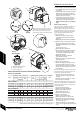
A- B leed & p ressure g auge p ort
B - Pressure adjustment
C- V acuum gauge port
RIEL LO
RD B OI L P UMP
C
B
A
Boiler 18/25 RDB 2.2
0.60 6 0 ° ES
0.75 8 0 ° ES
11 5
115
110
1. 5 8
1. 8 4
2. 15
1.96
2.33
2.72
75
77
82
11.0
12.0
12.5
4.5
2.5
3.75
18.0
21.5
25.0
18
21.5-25
18.5
22.1
25.7
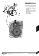
D
L
AIR
DAMPER
DISC
SETTING
BURNER
HEAD
(APPLIANCE)
(APPLIANCE)
18.5
15-18
21.5-25
LD 2X SH 12/18
27.5
30.0
N/A
N/A
T2 L/H 25/32
T2 L/H 25/32
D
Adjust position of air damper discs to suit
burner output (see chart below), located as
above. Access by removing the two star
screws (SC) to release the air inlet manifold.
SC
SC
12/18 18/25
0.55 8 0 ° EH
LD 2X SH 12/18
LD 2X SH 12/18
T2 SH 18/25
T2 SH 18/25
T2 SH 18/25
2
D
K
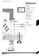
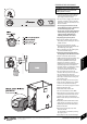
STARTING THE APPLIANCE
2 Remove plastic cover from the burner casing.
Fit a suitable pressure gauge to port (A) on
the oil pump.
Adjust the air shutter (L) and pump pressure
(B) as shown in the table opposite. The
burner should ignite following a pre-ignition
period of approx. 15 seconds.
If changing the burner output, check the
position of the air damper disc is correct to
the output as shown in the table below.
NOTE: For 25/32 appliance see following
page.
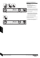
Boiler lockout indicator on:
If the burner fails to establish a normal firing
pattern or flame failure occurs the flame
monitoring photocell mounted in the burner
body will alert the burner control box to shut
the burner down and provide a safe lockout
state indicated by the illumination of the
lockout indicator (D).
Wait 2 minutes then press the lockout
reset button (D) to initiate another start
sequence.
Repeat procedure until a flame is established.
3Start and run for 3 minutes then switch off.
Check for after-spurting from the nozzle,
indicated by oil saturation on the combustion
head (G).
If after-spurting occurs:
Release the burner retainer (F).
Remove the burner, combustion head (G).
and electrodes, hold the burner vertical
to unscrew the nozzle and fill the nozzle
holder with kerosene.
Refit nozzle, electrodes, combustion
head (G) and the burner.
Restart and run for 3 minute intervals until
after-spurting stops.
4Start and run for 20 minutes.
Remove sampling point cap (K) to check
the smoke reading is between 0-1. If the
smoke level is above 1, check the combustion
settings are correct and the oil nozzle is in
good condition.
Note: smoke readings may be inaccurate until
the smoke from burning organic binder in the
access door insulation has ceased.
Check the CO
2
levels and adjust the air
shutter (L) setting according to the table
opposite.
Check the flue gas temperature is close to
the values shown in the table.
If the flue gas temperature is too high and the
baffles are correctly fitted, then reduce the oil
pump pressure (B) 5-10p.s.i. to compensate
for nozzle variations.
Turn off the electrical supply.
Isolate the oil supply to the burner.
Remove the oil pressure gauge.
Refit the blanking plug (A).
Check and rectify any oil leaks.
5Switch on the oil supply.
Switch on the electrical supply.
Restart the boiler and run for 5 minutes.
Recheck the CO
2
levels and if required,
adjust the air shutter setting (L) to obtain
the correct CO
2
level.
Refit the sample point cap (hand tighten
only, do not over tighten) and refit the burner
cover.
* 25/32 model for 25kW remove the plastic air guide (see following page ).
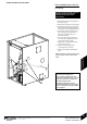
STARTING THE APPLIANCE
INSTALLATION & SERVICING INSTRUCTIONS FOR WORCESTER GREENSTAR CAMRAY EXTERNAL &
EXTERNAL SYSTEM 12/18-18/25-25/32
8 716 115 667a (05.2009)
37
COMMISSIONING