
Instruction manual


INSPECTION AND SERVICE
INSTALLATION & SERVICING INSTRUCTIONS FOR WORCESTER GREENSTAR CAMRAY EXTERNAL &
EXTERNAL SYSTEM 12/18-18/25-25/32
8 716 115 667a (05.2009)
43
SERVICING
& SPARES
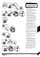
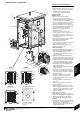
1 Clean the Burner:
Remove the air intake cover (A) and clear
any debris from the air intake and air damper.
Disassemble the burner to allow access to
the fan impeller.
Check the condition of the gaskets between
these parts and replace if necessary.
Note the position of the air damper
adjustment and check the air damper moves
freely.
Clean both sides of the fan impeller and
remove any debris from the burner housing.
Check that the impeller rotates freely.
Reassemble the components.
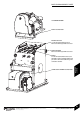
Remove the combustion head (B) and
thoroughly clean any deposits.
IMPORTANT: Before removing or fitting a
nozzle (C), loosen screw (D) and move
the electrodes (E) forward.
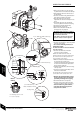
After refitting check that the electrode
gaps are correct, as shown opposite.
Remove the nozzle (C).
Check the nozzle holder is clear of any debris
and clean if neccessary.
Fit a new oil atomising nozzle (C) to
match boiler output.
DO NOT dismantle the nozzle and DO NOT
clean the nozzle tip.
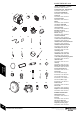
Check the electrodes (E) and reset if
necessary as shown opposite.
NOTE: The 12/18 model has a brass air
deflection washer and locating circlip behind
the nozzle. These must be in place for the
correct operation of the burner.
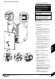
Refit the combustion head (B). Check that
the nozzle (C) lies centrally in the
combustion head (B) and the head settings
are as shown. Ensure that the photocell is
lined up with the sight hole.
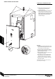
Withdraw the photocell (F) from its housing
and wipe clean.
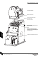
Remove the oil pump internal filter, clean in
kerosene and reassemble.
The internal filter is accessed by removing
screws (G) and the oil pump cover (H).
Replace the standard flexible oil hose
at every annual service to prevent the
possibility of leakage due to ageing.
Reassemble the burner components.
Check the O-ring seal located around the
combustion head and replace if necessary.
This seal must be in good condition,
seal failure will cause flue gases to
escape into the cabinet.
INSPECTION AND SERVICE
D
(on 12/18 and 18/25 models only)
G - Retaining screws - cover
H - Cover - oil pump
G
RIELLO
RDB OIL
H
F
A
B
5mm
5mm
C
E
B
3.5 - 4.0mm
C
E
E
2.0 - 2.5mm
C
Electrode gap
C
E
(D on 25/32 model only)
(on 12/18 model only)
Brass air deflection washer
Locating circlip