
Instruction manual


FAULT FINDING
& DIAGRAMS
FAULT FINDING
INSTALLATION & SERVICING INSTRUCTIONS FOR WORCESTER GREENSTAR CAMRAY EXTERNAL &
EXTERNAL SYSTEM 12/18-18/25-25/32
8 716 115 667a (05.2009)
55
Boiler not
operating
with a
heating /
hot water
demand
Burner
motor runs?
Lockout
within 1
second?
Replace
control box
Replace
motor/pump
Check boiler
controls &
supply
Replace
motor
230V to
control box?
Motor or
pump
seized?
Photo cell
functional?
Solenoid coil
functional
(100Ω)?
Replace
photo cell
Motor gives
50 Volts on
white wire?
Lockout
after 12 sec
purge?
Replace
control box
Replace
solenoid coil
Replace
motor
Ignition
spark
proved?
Oil to pump?
Drive
coupling
broken?
Purge
pressure
1-2 bar?
Pump
produces
pressure?
Replace
pump stem
valve/pump,
pressure
OK?
Replace
solenoid coil
Pipe to
nozzle
holder OK?
Replace
nozzle
Replace oil
pump
Replace
control box
Eectrodes &
leads OK?
Yes
No
NO
Yes
No
Yes
No
Yes
Yes
No
No
Yes
Yes
No
No
Yes
Yes
No
Yes
Motor 40Ω
between blue &
black wires ?
Replace
control box
Yes
Yes
No
Yes
No
Yes
No
No
No
Yes
No
Nozzle
atomising
fuel?
Combustion
air setting
correct?
Yes
Yes
Combustion
head set
correctly?
Solenoid operating?
Increase the pump pressure.
Pressure now OK?
Solenoid coil
functional
(100Ω)?
No
Solenoid
lead OK?
Yes
Yes
Replace
control box
No
If BF
remove
burner
snorkle tube
& retest.
Burner OK?
Flame off &
re-lights?
Yes
Photo cell
functional?
No
Yes
Replace
photo cell
No
Boiler or flue
blocked
No
Reseal BF
or reposition
terminal
Yes
Replace
control box
Yes
Replace
electrodes/
leads
No
Unblock or
replace pipe
No
Reset air
setting
Reset
combustion
head
NoNo
Yes
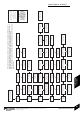
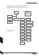
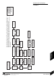
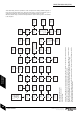
FAULT FINDING LOGIC FOR
535 SE/LD RDB CONTROL BOX
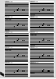
All resistance measurements are actual measured values and some variation is to be expected, therefore measured
values should be similar to but not necessarily identical to the given values.
The operation of the photo cell can be tested by measuring the resistance across the photo cell, it should be a high
resistance (greater than 10MΩ or open circuit) in the dark and low resistance (3kΩ or less) in light.
Burners on balanced flue systems can recirculate flue products resulting in the burner cycling, if this happens check the
flue system integrity and the terminal position.
These fault finding charts are provided to assist competent and suitably qualified engineers to
locate and rectify faults. Whilst every effort has been taken to ensure the information given is
correct and complete we cannot guarantee that every eventuality has been covered.
Worcester, Bosch Group cannot be held responsible for costs incurred by persons not deemed
to be competent.
Mesure all 230V tests between
Neutral (N) and the pin, wire or
terminal specified.