26CDi XTRA WALL MOUNTED CONDENSING COMBINATION BOILER FOR CENTRAL HEATING AND MAINS FED DOMESTIC HOT WATER INSTALLATION AND SERVICING INSTRUCTIONS GC NUMBER 47 311 41 (N.G.) GC NUMBER 47 311 42 (L.P.G.) Worcester supports the Benchmark code of practice BOILER OUTPUT Automatic Modulating Control To Domestic Hot Water and Central Heating Minimum 6.7 kW Maximum 26.
Contents 1. 2. 3. 4. 5. 6. 7. 8. 9. Installation Regulations .............................................. Page 1 Introduction.................................................................. Page 1 Technical Data .............................................................. Page 4 Siting the Appliance .................................................... Page 6 Siting the Flue Terminal .............................................. Page 8 Air Supply ......................................................
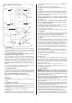
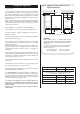
as the minimum clearances stated in Section 6: Air Supply, are maintained. Do not place anything on top of the appliance. The clearances specified for servicing must be maintained. See fig. 2. Fig. 1. Appliance water flow diagram. Automatic Air Vent Secondary High Efficiency Heat Exchanger 2.10 FLUE The appliance has a multi-directional horizontal fanned flue system. The Standard Flue assembly length is from 100mm to 1000mm.
2.13 SHOWERS, BIDETS, TAPS AND MIXING VALVES Hot and cold taps and mixing valves used in the system must be suitable for operating at mains pressure. Thermostatically controlled or pressure equalising shower valves will guard against the flow of water at too high a temperature. If using a pressure equalising valve, set the Domestic Hot Water temperature control knob to the “MAX” position.
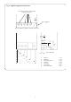
Table 3 Available pump head. Mode of operation Gal/Min. Temperature rise across heating flow and return 8.7 1.9 11°C (20°F) 18.8 5.1 1.1 20°C (37°F) 2.0 6.6 23.0 5.1 15°C (27°F) 3.5 11.6 18.6 4.1 20°C (37°F) Boiler output. Head Min, flow rate kW Btu/h Metres Feet Non-cond. 6.7 (22,860) 5.4 17.8 Condense 7.2 (24,566) 5.7 Non-cond. 24.0 (81,888) Condense. 26.0 (88,712) L/min. Table 4 Specifications Central heating flow fitting.
4. Siting the Appliance Fig. 2. Appliance casing dimensions and required clearances. See figs. 2 and 3. 4.1 The appliance may be installed in any room although particular attention is drawn to the requirements of the current l.E.E. Wiring Regulations BS 7671 and, in Scotland, the electrical provisions of the Building Regulations applicable in Scotland, with respect to the installation of appliances in rooms containing baths or showers.
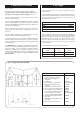
Fig. 3. Appliance pipework connections Screw driver required to operate Valves. Valves shown closed. F Rear of appliance A B C D E G View on underside of appliance showing connections 85 (G) 195 (F) 110 (G) 61 A B 91 (A, B, C, D, and E) C D A B C D E F G E F G 7 CH Flow DHW Out Mains Cold Water In Gas Inlet CH Return Safety Relief Condensate Drain = = = = = = = 62.5 127.5 192.5 257.5 322.5 382.
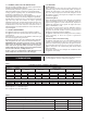
5. Siting the Flue Terminal 6. Air Supply See fig. 4 and 15. 6.1 The appliance does not require a separate vent for combustion air. 5.1 The flue must be installed as specified in BS 5440:Part 1. Important. The flue must be installed with an incline of 2l/2° (44mm per metre length) towards the appliance. See fig. 15. 6.2 The appliance can be fitted in a cupboard with no vents for cooling but the minimum clearances must be increased to those given below.
assembly. (The grey knob for the filling loop is packed in the hardware pack and should be fitted as shown.) Insert the bayonet end of the filling key into the corresponding cut-outs in the filling loop housing and twist to lock the key in place. Turn the grey knob anti-clockwise to allow water ingress and fill until the required pressure is reached.
8. Domestic Hot Water 9. Electrical See figs. 9, 10, 11, 12, 13, 14 and 27. 8.1 The following are general requirements and, if necessary, reference should be made to the local Water Company before fitting the appliance. 9.1 MAINS SUPPLY. 230 V~, 50 Hz, 180 watts. External Fuse. 3A. Internal Fuses: T 2A (F1) and T 1.25A (F2). Spare internal fuses are supplied at the rear of the facia, next to the pressure gauge. 8.2 MAINS COLD WATER INLET.
Fig. 9. Mains electricity connections. 230V L N Ns LS LR Brown ST12 Blue Strain relief clamp Green/yellow Fig. 10. Wiring diagram.
LIVE IN ST12 Pin N ST12 Pin L Fuse F1 (2A Slow) On/Off switch 12 ST1 Centre Pin Low High ST1 Pin L Convert AC to low voltage electronics ST15 Pin L REL 4 ST8 (LR) Spark Red Indicators Red Settings Electronics/ microprocessor (Safety Low Voltage) REL 3 Optional link Room thermostat ST8 (NS) Transformer Fuse F2 (1.
Fig. 12. 230 V room thermostat connections. NS LS LR Spare ST8 Switched live Live Neutral Remove link Fig.13. 230 V programmer connections. NS LS LR Spare Switched live Live Neutral ST8 Motor Fig. 14. 230 V room thermostat and programmer connections.
10. Installation Fig. 15. Flue Options 21/2° The appliance is supplied suitable for fitting to a sealed primary system only. Rear flue length 100 to 390mm 10.1 Flue Options NOTE: Flue system inclines downwards towards the appliance Refer to fig. 15. IMPORTANT 21/2° Two flue options are available: Appliance i) Standard Flue To suit rear or side flue installations where the flue length measured from the appliance casing to the outside of the wall is from 100mm to 1000mm.
Fig. 16. Marking the Flue Positions for all Flue Options and Fixing the Wall Mounting Plate Side flue installation. This is the side flue centre point position Rear flue installation. This is the rear flue centre point position Top fixing screws (2) 197 mm 211mm 21/2° Incline * 822mm 800mm Side flue installation. Draw a line inclining towards the appliance by 21/2° in the appropriate direction. Mark horizontal line along here.
Slide the appliance onto the pre-plumbing manifold ensure the three pegs are located correctly. Secure with the two M6 nuts and washers at the top and screw the appliance to the manifold at the bottom, using the three retaining caps and M6 bolts. See fig. 19. To access pegs and caps remove the bottom panel. Unscrew the automatic air vent cap. See fig. 20.
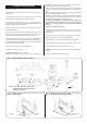
When assembling air and flue ducts, ensure they are correctly located in the socket joints. Refer to figs. 23 and 24. Take care to seal all the flue joints where indicated. To seal the flue joints, disengage the joint and apply a smear of silicone sealant around the duct. See figs. 23 and 24. On final assembly, the air duct must be adequately supported. Air duct support brackets are available as an optional extra. See Section 10.1 for air duct support bracket part number. 10.
flue terminal. f) Drill through the holes in the flue terminal into the air duct with the drill provided. Fix the flue terminal temporary with the screws provided. NB: When assembled correctly the flue duct will extend 44mm beyond the air duct. See fig. 23. g) Undo the screws and ease the air duct clear of the flue terminal. Apply a bead of silicone sealant, provided, around the groove in the air duct. Reassemble the air duct into the flue terminal. Fix permanently with the original screws.
Fig. 26. Terminal Assembly for Internal Fitting of the flue Fig. 25. Duct and Terminal Assembly for Internal Fitting of the Flue Rubber sealing gasket Flue duct Flue terminal Flue terminal 21/2° incline Air duct Flue duct supplied already assembled to the flue terminal 10.7 Final Installation Clamping ring 11. Commissioning Check that all the water and gas connections have been tightened. If a facia mounted programmer is to be fitted follow the programmer instructions.
11.1. Appliance and central heating system preperation Fig. 27. Appliance Casing, Facia Controls and Location of Equipment. Remove the cabinet front panel. Check that the electrical supply and the gas service to the appliance are off. See fig 3. Check that all the water connections throughout the system are tight. Open the system valves at the appliance. See fig 3. Open all the radiator valves, fill the system and vent each radiator in turn.
Undo the two upper screws and hinge down the facia, taking care not to damage the pressure gauge capillary tube or electrical connections. See fig.27. Setting the Burner Pressure Check that all the radiator valves are open. Set the room thermostat and the Central Heating Temperature Control to maximum. Check that the sealed system is pressurised and set to the required pressure as indicated on the gauge. Set the Operating switch (or Programmer) to HEATING and WATER.
Domestic Hot Water Commence by opening a hot tap near to the appliance. Gradually close the hot tap and check that the burner pressure drops. Fully open the tap and check that the burner pressure rises. Fully close the tap and check that the burner goes off. The fan may continue running until the appliance has cooled to a pre-set temperature. Turn off the gas service cock and the electrical supply to the appliance. Drain the system while the appliance is still hot.
12.6 If an external programmer has been fitted which has a programmable domestic hot water facility then it is suggested that this be set to Continuous or the equivalent. Remove the sealing screw on the flue turret. See fig. 20. Insert the probe into the measurement gap up to a depth of 50mm. Seal any gaps. Expected measurements should be between: CO: 0.001 and 0.005%. CO2: 7.0 and 8.5%. After taking the measurement: Replace and tighten the sealing screw. Turn the Mode Switch back to the ‘normal’ position.
NOTE: The flame sensing lead is attached to the burner. When the burner is removed ensure this lead is fed through the inner casing. Remove the grommet seal to allow the plastic connection to pass through the inner casing. Unscrew the G 3/4 union nut on top of the gas valve and retain the sealing washer. Unscrew the front burner fixing screw. Lift the burner and ease the union nut through the inner casing sealing grommet. Remove the burner assembly clear of the inner casing.
IMPORTANT: The following components are secured to the appliance with clips, wire clips, screws, union fittings or ‘O’ ring seals to ensure the joints are sound. When reassembling ensure the sealing washer located in the union nut is replaced. If the washer is damaged it must be replaced. Ensure the sealing grommets are fitted correctly and seal the inner casing. See figs. 32 and 37. 13.4 SERVICING OF COMPONENTS Clean the Fan Any dust or fluff should be removed with a soft brush or by blowing.
2. Air Flow Pressure Switch. See fig.34. Check that the electricity supply to the appliance is turned off. Remove the cabinet front panel and hinge the facia down into the Service Position, as described in Sections 13.3 (a) and 13.3 (c). Note the position of the tubes and electrical connections. Carefully pull off the sensing tubes and the electrical connections from the switch. Undo the two screws located under the gas valve and remove the switch with the support bracket from the appliance.
Carefully pull off the two electrode leads. Unscrew the M4 extended nut and remove the spark electrode assembly from the burner and discard. Fit the replacement electrode in the reverse order, check the spark gap is 3 to 4mm. Reassemble the appliance in the reverse order. Fig. 35. Combustion Chamber Insulation Combustion chamber front and side assembly Side insulation pad Side insulation pad 10. Flame Sensor. See figs. 32 and 36. Remove the burner as described in Section 13.3 (h).
12. Central Heating Sensor. See figs. 32 and 33. Check that the electricity supply to the appliance is turned off. Remove the inner casing cover as described in Section 13.3 (b). Carefully pull off the two leads from the sensor. Pull off the sensor and spring retaining clip from the pipe. Discard the sensor retain the clip. Fit the replacement sensor in reverse order with a layer of heat sink compound between the faces. Refit the leads. Polarity is not important.
16. Filling Loop. See figs. 37 and 39. Check that the electricity supply to the appliance is turned off. Drain the central heating circuit as described in Section 14.3 (a). Hinge the facia panel down into the Servicing Position as described in Section 13.3 (c). Drain the central heating circuit as described in Section 14.3 (a). Remove the screw securing the filling loop to the underside of the water diverting valve. Remove the clip retaining the filling loop to the plastic flow manifold.
18. Water Diverting Valve Micro Switch Assembly. See figs. 37 and 40. Ease the water diverting valve out of the plastic manifold. Remove the securing bracket from the valve and the water filter from the valve cold water inlet. Retain the plastic manifold, fixing screws, support bracket and water filter. Discard the water diverting valve. Reassemble the original support bracket, water filter and new ‘O’ ring seals to the replacement valve.
Feed the pipe and sealing grommet clear of the inner casing. Retain all components and securing clips removed. Carefully pull off all the connectors. Disconnect the mains supply lead at terminal ST 12 and the earth connection at the back. Pull off the three plastic control knobs. Take care not to damage the knobs when pulling off. Retain the knobs. Hinge down the facia panel into the Servicing Position as described in Section 13.3 (c). Remove the plastic water cover.
25. Secondary Heat Exchanger. See figs. 32, 33, 34, 35, 36, 37, 39, and 43. Check that the electricity supply to the appliance is turned off. Drain the central heating circuit as described in Section 14.2 (a). The secondary high efficient heat exchanger is housed in a stainless steel box. The assembly is located inside and at the rear of the inner casing. Fig. 43.
Reassemble the appliance in the reverse order. Ensure all gasket seals and ‘O’ connections are made correctly. Open the valves fill and re-pressurise the system as described in Section 11.1. 26. Condensate Syphon. See fig. 37, 43 and 44. Check that the electricity supply to the appliance is turned off. Hinge down the facia panel into the Servicing Position as described in Section 13.3 (c). Disconnect condensate drain pipe from condensate syphon.
15. Short Parts List Key No. G.C. No.
201 (NG OR LPG) 109 96 (NG OR LPG) 35
MAIN SWITCH ON Green Light On Room thermostat and/or mains programmer (or link) On AND AND Electronic facia programmer (if fitted) On AND ST13 link in AND CH control knob On CENTRAL HEATING DEMAND CH light on. CH light On. Pump On. on. Pump FanOn high 3 Fan low/ ignition seconds then sequence. low /ignition Burner light sequence. On. Burner light on. Three minute wait Two minute minimum burner pressure then ramp up pressure over next one minute Gas valve Off. (CH light still on.
MAIN SWITCH ON Green Light On Flow switch On (Top open) DOMESTIC HOT WATER DEMAND (Priority over CH demand) HW light on. HW light On. Pump On. on. Pump FanOn high 3 Fan high/ ignition seconds then sequence. low /ignition Burner light sequence. On. Burner light on. Ten second wait Four second ramp to max. gas pressure Gas valve Off. (HW light still on.
OVERRUN FUNCTION Within four minutes of last hot water demand AND AND primary temperature above 80°C If heat demand has occurred in last 30 minutes Run pump until primary drops to 80°C If heat demand has NOT occurred in last 30 minutes Run fan until primary drops to 80°C If primary temperature still increases above 90°C Run pump for two seconds AUTOFROSTAT FUNCTION No demand and primary temperature below 8°C Internal “Autofrostat” demand Wait in normal off state for 30 minutes Run pump for four
17.
Is the facia on/off switch turned on? `(Clockwise) No Turn switch on. FAIL POINT A Yes Is there a 230V AC live supply across Terminal ST12 pins L and N No Check electrical supply to boiler. Yes Has fuse F1 blown? No Replace control board (Section 14.3.23) Yes Replace fuse and investigate cause. Suggestions: Cable damage, connections to (or faults within) pump, fan, external 230V controls, transformer or board.
With CH control knob fully clockwise, does the boiler ignite and appear to run normally in central heating mode? No Is there 230V AC across terminal ST8 pins LR and N? No There is no heat demand. Check room thermostat or mains programmer (or link). Yes Yes Red diode is damaged. Replace control board. (Section 14.3.
FAIL POINT F Is the boiler in a very cold environment (less than 5°C)? Yes Drop down the facia. Is the gas valve mode switch in the normal position? No Yes Replace control board. (Section 14.3.23) Note: A wet board could cause this fault. Boiler is running in “Autofrost stat” mode. See Section 17. Is the boiler fully water pressurised and is all air vented? FAIL POINT G “Primary Overheat” No No Rectify fault. Yes Reset the controls and restart the boiler.
Is the gas supply connected and at the correct pressure? No Rectify gas supply problem. Yes Remove front panel. Reset and restart the boiler. Can a flame be seen through the spy glass? No Remove inner cover. Reset and restart the boiler. Does a spark occur across the electrodes? No Are the electrodes and gap and connections in good order? No Repair or replace electrodes (Section 14.3.9) or HT leads Yes Replace control board. (Section 14.3.23). Yes Turn off boiler.
Is the multiway connector at board position ST16 pushed fully home on to the board? No Push fully home. FAIL POINT I “Sensor Fault” Yes Remove multiway connector from board position ST16. Test resistance across contacts 17 and 18 (yellow wires). Is it between 1 kohm and 30 kohm? No No Check or replace DHW sensor. (Section 14.3.13). No Is there continuity from contacts 12 and 13 to CH sensor? No Yes Yes Repair or replace harness. Yes Yes Test resistance across contacts 12 and 13 (red wires).
Does the fan run before the fault occurs? No Turn off boiler. Is there continuity across the C and NO terminals of the air pressure switch (where green wires are fitted)? No Remove the fan connector from board position ST1 and restart the boiler. Is there mains 230V across the centre (L) and left (N) tracks at ST1? Note: Take care not to short L to N. Yes Yes Yes FAIL POINT J “Air Pressure Fault” Air pressure switch is shorting. Replace switch. Section 14.3.
FAIL POINT K Light indication during fault not covered by above details. Control board is likely to be wet or damaged or malfunctioning. Check for wet board or connections. Dry and re-use or replace control board. (Section 14.3.23). Hot water temperature always too hot during a demand (not regulating). Hot water sensor could be off or poorly fixed to pipe. Repair or replace sensor. (Section 14.3.13).
18. Conversion Instructions GAS VALVE Max 2mm Allen key ONLY COMPONENTS SUPPLIED BY WORCESTER SHOULD BE USED. ONLY COMPETENT PERSONNEL SHOULD ATTEMPT THE CONVERSION. CONVERSION FROM NATURAL GAS TO LPG SHOULD NOT BE CARRIED OUT ON APPLIANCES INSTALLED IN A ROOM OR INTERNAL SPACE BELOW GROUND LEVEL Min 3mm Allen key 1 Conversion Kit LPG to NG Conversion Kit NG to LPG 7 716 192 307 7 716 192 308 1. Ensure the gas service cock is turned OFF and the electrical supply is ISOLATED. 6 2.
BENCHMARK No. GAS BOILER COMMISSIONING CHECKLIST COLLECTIVE MARK BOILER SERIAL No. CONTROLS NOTIFICATION No.
SERVICE INTERVAL RECORD It is recommended that your heating system is serviced regularly and that you complete the appropriate Service Interval Record Below. Service Provider. Before completing the appropriate Service Interval Record below, please ensure you have carried out the service as described in the boiler manufacturer s instructions. Always use the manufacturer s specified spare part when replacing all controls SERVICE 1 DATE SERVICE 2 DATE ENGINEER NAME COMPANY NAME TEL No.
This manual is to be used in conjunction with the variant part number of the bar code below: www.worcester-bosch.co.uk Bosch Group Worcester, Bosch Group, Cotswold Way, Warndon, Worcester WR4 9SW. Telephone: 01905 754624. Fax: 01905 753130. Technical Helpline 08705 266241. Worcester, Bosch Group is a trading name of BBT Thermotechnology UK Limited.