
Technical data
Check that all the water and gas connections have been
tightened.
If a facia mounted programmer is to be fitted follow the
programmer instructions.
Hinge down the facia as described in Section 13.3 (c).
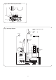
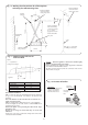
Connect the mains electrical supply to the appliance at terminal
ST 12 (see fig. 9). Connect any room and/or frost thermostats.
The electrical leads must pass through the appropriate space in
the control panel and be fixed with the cable clamps provided.
See figs. 12 and 13. Refit the facia panel.
Test the gas supply pipework up to the appliance for soundness
as indicated in BS 6891.
Refer to Section 11 Commissioning for a full description of the
filling, venting and the pressurising of the system.
If the appliance is not to be commissioned immediately, replace
the cabinet front panel. Check that the gas supply, the electrical
supply and the water connections are all turned off.
If the premises are to be left unoccupied during frosty conditions,
then drain the appliance and system. For short inoperative
periods, leave the appliance under the control of the built in frost
thermostat or the remote frost thermostat (if fitted) or leave
operating continuously with the room thermostat set at 6°C.
Benchmark Water Treatment: For optimum performance after
installation, this boiler and its associated central heating
system should be flushed in accordance with the guidelines
given in BS7593:1992 - Treatment of water in domestic hot
water systems. Full instructions are supplied with proprietary
cleansers sold for this purpose. If an inhibitor is to be used
after flushing, it should be used in accordance with the
inhibitor manufacturers instructions.
Suitable flushing agents and inhibitors are available from Betz
Dearborn Tel: 0151 4209563 and Fernox Tel: 01799 550811.
Instructions for use are supplied with these products.
Summary.
The appliance is dispatched with the controls set to provide a
maximum output for the domestic hot water and central heating
of:
Non-condensing mode 24.0kw (81,900 Btu/h).
Condensing mode 26.0kw (88,760 But/h).
The appliance modulates automatically to satisfy lower heat
loads.
Domestic Hot Water System:
Check that the mains water supply has been fully flushed out at
installation.
Central Heating System:
Check that the central heating system has been fully flushed out
at installation.
Gas Service:
The complete system, including the meter, must be inspected
and tested for soundness and purged as indicated in BS 6891.
In the event of a leak, or suspected leak, at the 'O'ring seal on
the main appliance manifold, connect a manometer to the
test point on the inlet to the multifunctional gas valve. A gas
leak can be traced in this section to either a visible joint the
'O'ring seal.
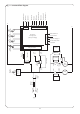
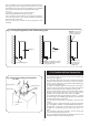
10.7 Final Installation
19
2
1
/
2
°
incline
Flue terminal
Air duct
Flue duct
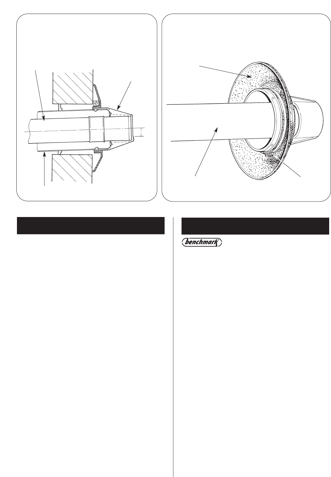
Fig. 25. Duct and Terminal Assembly
for Internal Fitting of the Flue
Fig. 26. Terminal Assembly for Internal
Fitting of the flue
Flue
terminal
Clamping ringFlue duct supplied already
assembled to the
flue terminal
Rubber sealing gasket
11. Commissioning